Description
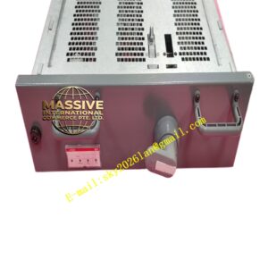
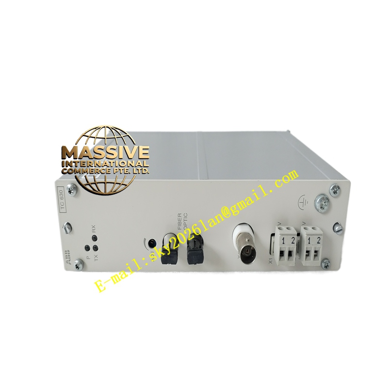
ABB TC630
- Technical Specifications (typical SPU01 — TC630 equivalent):
- Input: 24 V DC (18–30 V), typ. fused 2–5 A slow-blow external
- Output: 5 V DC ±2 % (max 3 A for SPU01), 24 V DC UP (pass-through, fused/jumpered)
- S100 Bus Termination: 95 Ω ±1 % (enabled via jumper or plug — set to ON if this is last S100 node)
- Power Dissipation: ≤10 W (quiescent + load)
- Mounting: On S100 termination unit (TA563 etc.) — leftmost or rightmost position (typically left end of S100 rack)
- Indicators: Input PWR (green), 5 V OK (green), Fault (red)
- Operating Temp.: 0 °C to +55 °C
- Dimensions: ≈45 mm (W) × 119 mm (H) × 102 mm (D) — same width as one S100 module
- Functional Features / Application / Material / Structure / Working Principle / Installation / Precautions:
- Every S100 I/O cluster needs one SPU01 — for redundant clusters (rare) two SPU01 in different racks with diode-OR may be used
- Install at one end of daisy-chain — enable termination jumper if it is the last device on bus
- Size PSU for ∑ module currents: each DI/DO/AI module draws ~50–150 mA @24 V (logic) + any output load current (DO relay coils powered from UP terminal — count separately)
- Precaution: Forgetting to enable termination (or having terminator at wrong end) causes bus communication errors (CRC, timeouts). If rack is NOT the last node (e.g., another rack daisy-chained after it) → disable termination on SPU01 (move jumper to “OFF”) & place 95 Ω plug at true last node. Verify bus voltage (should see ≈5 V DC between logic + / GND on test points if powered correctly).