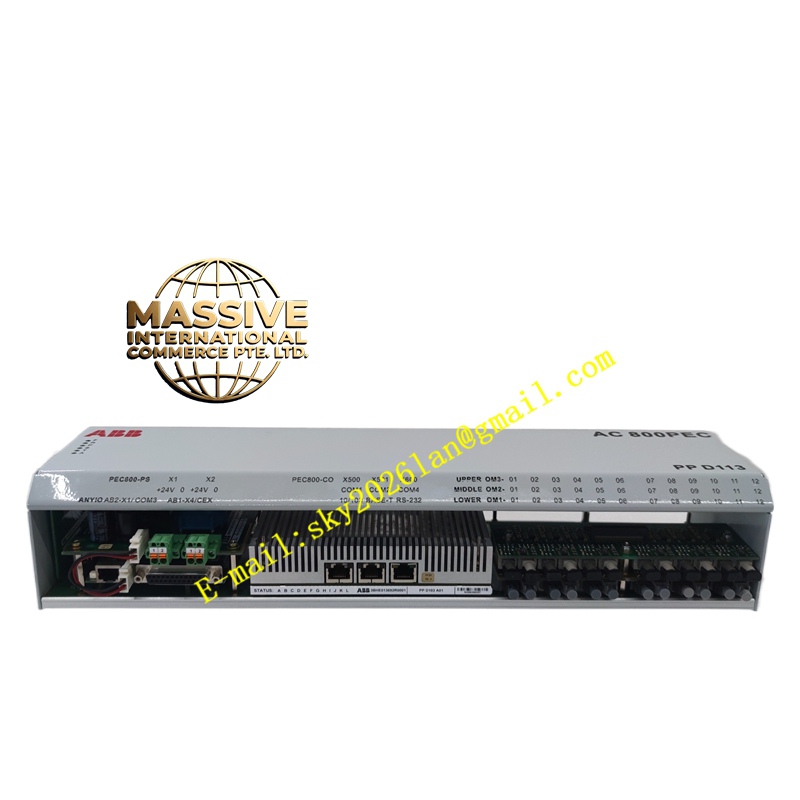
Description
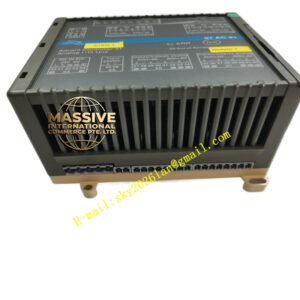
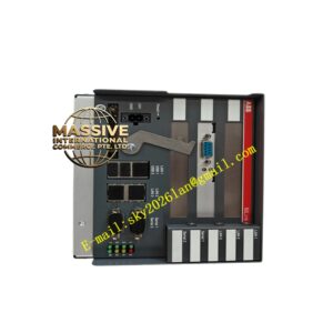
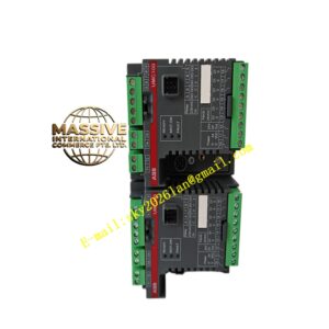
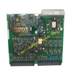
ABB QUINT-PS1AC5
- Technical Specifications (typical QUINT-PS/1AC/24DC/5 — 5 A version):
- Input Voltage: 85–264 V AC (47–63 Hz) / 90–350 V DC
- Output Voltage: 24 V DC ±1 %, adjustable ±5 % via front pot
- Rated Output Current: 5 A (120 W); 10 A (240 W), 20 A (480 W) also common
- Output Ripple: <50 mV pp
- Power Boost: 120 % In for 5 s (start-up / inrush handling)
- Selective Fuse Breaking: Capable of breaking downstream short with std. automotive fuse (characteristic aids discrimination)
- Signaling: DC OK LED + transistor output (collector open — NPN) for remote alarm (optional on -SC version; base version may have LED only)
- Hold-up Time: >20 ms @ full load (typ. 40 ms)
- Efficiency: >89 %
- MTBF: >500,000 h (Telcordia SR-332)
- Mounting: 35 mm DIN rail (EN 60715), NS 35/7.5 or NS 35/15
- Dimensions (5 A): ≈70 × 124 × 117 mm (W × H × D)
- Operating Temp.: –25 °C to +70 °C (derate linearly above +60 °C)
- Certifications: CE, UL 508, cULus, GL (marine), ATEX (for use in Zone 2 if system certified), CB
- Functional Features:
- Wide input — suitable for global site mains (100–240 V AC auto-ranging)
- PowerBoost & selective fuse breaking simplify downstream protection sizing
- Long MTBF, conformal-coated PCB option (some QUINT versions)
- Optional backup module (QUINT-BAT/QUINT-CAP) for bridging short mains failures (10 s – 30 min)
- N+1 redundancy: two units diode-OR’d (or with QUINT-ORING module) → no single PSU failure stops I/O rack
- Application Scenarios:
- Powering S800 I/O rack (PPD113A01 input) — size for ∑ module currents + margin (typically 10 A or 20 A PSU for medium racks; 5 A for small 1–2 module rack)
- Control voltage for interposing relays, safety relays (D674A905U01 etc.), panel indicators
- 24 V DC for HMI (PP836), gateways, serial converters in panel
- Material & Structure / Working Principle / Installation / Precautions:
- DIN-rail mount in panel; leave ≥50 mm above/below for convection
- Connect L/N to AC input terminals (observe PE to PE terminal — mandatory!)
- Connect +V / –V to load (S800 rack PPD113 UP terminals, or DC distribution terminal block)
- For N+1: use two QUINT PSUs + diode OR module (or use internal diode-OR in PSU if equipped) — size each for full load
- Set output voltage to 24.0–24.5 V DC (some prefer 24.3 V to compensate for cable drop — check system spec)
- Verify DC OK LED green after power-up; check voltage at load end under load
- Precautions:
- Always fuse AC input (2 A slow-blow typ. for 5 A version) & consider DC output fuse per load group
- Do NOT exceed max continuous load (5 A for 5 A version) — oversize if inrush / multiple modules draw high peak
- PE terminal MUST be connected — essential for safety & EMC
- For redundant config: ensure both PSU outputs connected via OR-ing diode — monitor both DC OK signals
- In high-vibration environments: check set-screw tightness on terminals periodically (vibration loosening)