Description
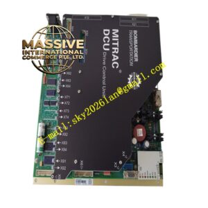
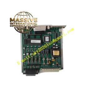
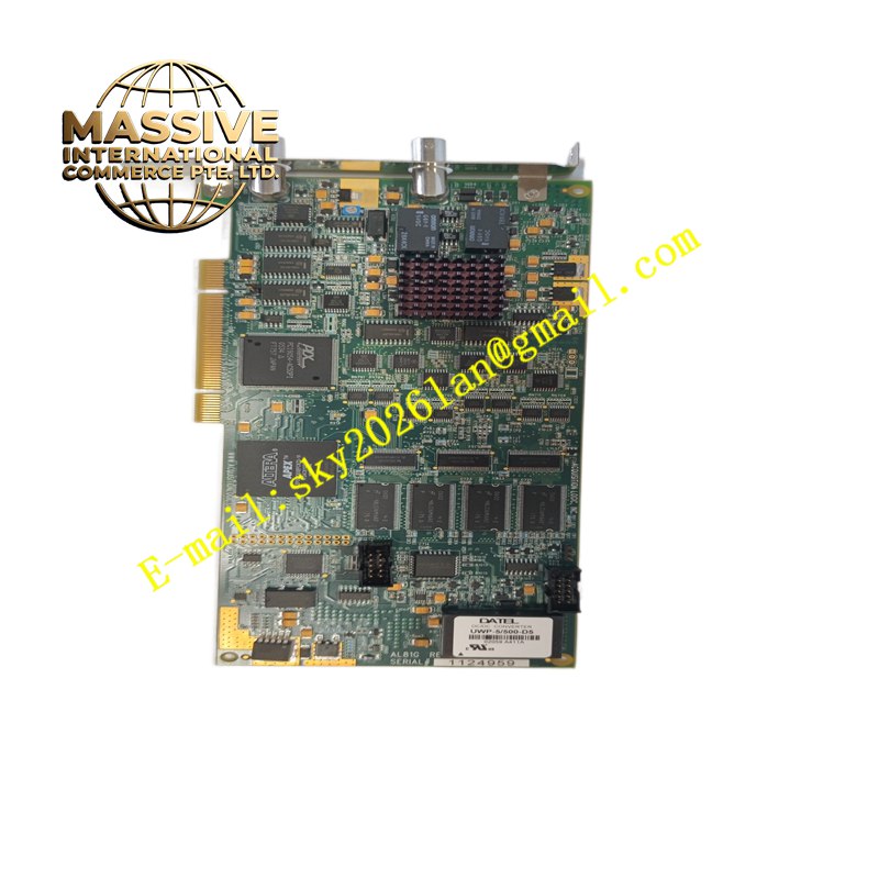
Alstom AL81G
Technical Specifications Multiple digital input and digital output channels; opto-isolation for each channel; input supports dry contact and 24V DC signal; output adopts relay contact type; isolation withstand voltage 2000V AC; 24V DC module power supply; operating temperature -20°C to +70°C; IP20 protection class.
Functional Features Detects the on-off status of field limit switches, auxiliary contactors and protection relays. Converts discrete status signals into digital data and transmits data to the main controller. Outputs contact signals to trigger circuit breakers, alarm relays and auxiliary interlock devices. Detects channel circuit abnormality and uploads fault information to the control system. Supports configuration of input logic polarity and output action mode.
Application Scenarios Power plant generator protection systems, substation auxiliary control, turbine auxiliary machinery interlock control, power grid protection cabinets, hydroelectric unit automation control.
Performance Parameters High isolation strength suitable for power industry harsh environments; fast input status capture speed; reliable relay contact action for long-term protection tasks; stable operation under electromagnetic surge interference in power stations.
Material Composition PCB substrate uses FR-4 flame-retardant multilayer printed circuit board; optocoupler chips and logic devices are industrial semiconductors; relay cores use high-reliability electromagnetic structures with silver alloy contacts; backplane gold finger contacts use gold-plated copper alloy; module housing is flame-retardant thermoplastic resin; terminal contact springs are nickel-plated copper alloy.
Structural Characteristics Vertical plug-in rack module matching Alstom control rack slots. Front panel is equipped with power, communication and channel status LED indicators. Rear gold finger connector connects to rack backplane for power and bus communication. Front screw terminal blocks accept field discrete signal wiring. Side locking buckle fixes the module to resist strong electromagnetic vibration in power stations.
Working Principle Field dry contact or DC voltage signals enter opto-isolation input circuits. The onboard logic chip identifies signal status and transmits status data to the main controller through the backplane bus. When the controller issues output commands, the onboard relay is energized or de-energized to change contact state and control external equipment. The module monitors power supply and channel circuit status continuously.
Installation Requirements Cut off the power supply of the control rack before installing the module. Insert the module into the designated rack slot and lock the buckle. Wire field switch and actuator circuits to terminal blocks following the schematic diagram. Configure input and output logic in the supporting engineering software. Complete contact action test and interlock verification after power on.
Precautions for Use Do not connect loads exceeding relay contact rated capacity. Separate field high-power wiring from module signal wiring. Check terminal tightness regularly during power station maintenance. Apply anti-static protection during module replacement.