



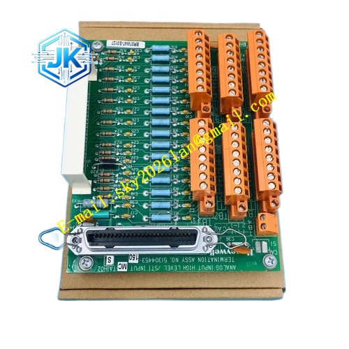
Description
Honeywell 51109456-200
Technical Specifications Input Power: 110V / 220V AC, 50/60Hz, jumper selectable Output Power Rails: 5V DC, 24V DC Maximum Output Power: 180W Power Factor: ≥0.92 Operating Temperature Range: 0℃ to 65℃ Storage Temperature Range: -40℃ to 85℃ Isolation Withstand Voltage: 2000V AC Relative Humidity: 5% to 95%, non-condensing Cooling Mode: Built-in temperature-controlled fan cooling
Functional Features It supports wide-range AC input and automatic voltage stabilization. It implements independent protection for each DC output rail. It supports redundant parallel current sharing operation with identical power modules. It monitors output voltage, output current and internal temperature in real time. It stores power fault records and alarm events in non-volatile memory. It provides power good enable signal for all rack functional boards. It uploads power fault and over-temperature alarm to HPM diagnostic console. It automatically adjusts fan speed according to internal temperature to reduce noise and dust accumulation.
Application Scenarios Power supply for HPM main control racks of petrochemical and chemical DCS control systems. Redundant power supply configuration for safety interlock and critical control racks. Replacement and spare stocking for aging power supply modules of legacy TPS control cabinets. Power supply for heavy-load UCN I/O racks with full channel configuration.
Performance Parameters Output Voltage Regulation Accuracy: ±1% Ripple Voltage: ≤30mV peak to peak Over-current Protection Response Time: ≤1ms Over-temperature Protection Trigger Point: 85℃ Redundant Current Sharing Deviation: ≤5%
Material Composition Metal casing: Cold-rolled steel sheet with electrostatic spray anti-corrosion coating High-frequency switching transformer and rectifier circuit components High-voltage electrolytic capacitors and low-ESR output filter capacitors Temperature-controlled DC fan assembly Precision voltage and current sampling chips Optocoupler isolation components Aluminum alloy heat sink for power switching devices
Structural Features Standard pluggable module structure, installed in dedicated power supply slot at the bottom of TDC3000 rack. Front panel is equipped with AC POWER indicator, 5V OUT indicator, 24V OUT indicator and FAULT indicator light. AC input terminal and DC output terminal are separated on different sides to avoid high-voltage and low-voltage signal crosstalk. Internal power switching devices are fixed on large aluminum heat sink for efficient heat dissipation. Fan air duct is designed to blow through heat sink and power circuit board to take away heat. All internal circuits are covered with conformal coating to resist dust and corrosive gas.
Working Principle AC input power enters the module through input terminals. The EMI filter circuit suppresses grid surge and high-frequency interference. The rectifier and PFC circuit convert AC power into stable DC bus voltage. The high-frequency switching circuit converts bus voltage into target 5V and 24V DC power. The filter circuit reduces output ripple and stabilizes output voltage. The sampling circuit continuously monitors output voltage, current and internal temperature. When working parameter exceeds protection threshold, the protection circuit cuts off corresponding output rail and triggers fault alarm. For redundant configuration, the current sharing circuit balances output load between two parallel power modules.
Installation Requirements Insert the module horizontally into the dedicated power slot of TDC3000 rack and lock the fixing latch. Select correct AC input voltage gear via internal jumper before power-on. Connect AC input cable to input terminals following live wire, neutral wire and ground wire marking. Verify fan rotation and all output indicator status after power supply switch-on. Check power reading and fault log on HPM diagnostic page.
Precautions Cut off AC input power before removing or replacing this power module. Ground terminal must be connected reliably to protective earth to avoid electric shock risk. Do not block the air inlet and outlet of the cooling fan, blocked air duct causes over-temperature shutdown. Only use identical model modules for redundant parallel configuration. Do not modify internal circuit components or protection parameters without engineering authorization.







