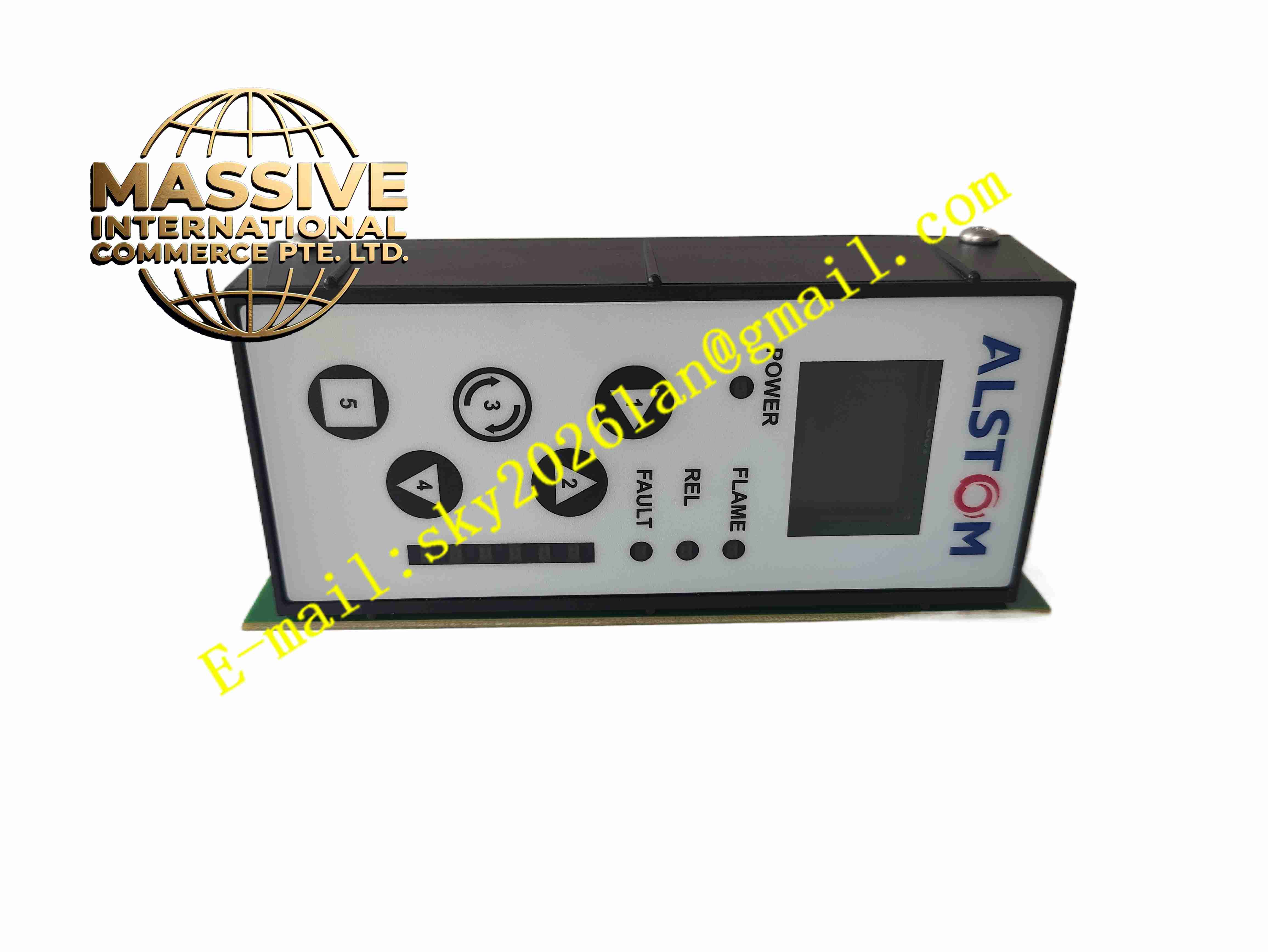
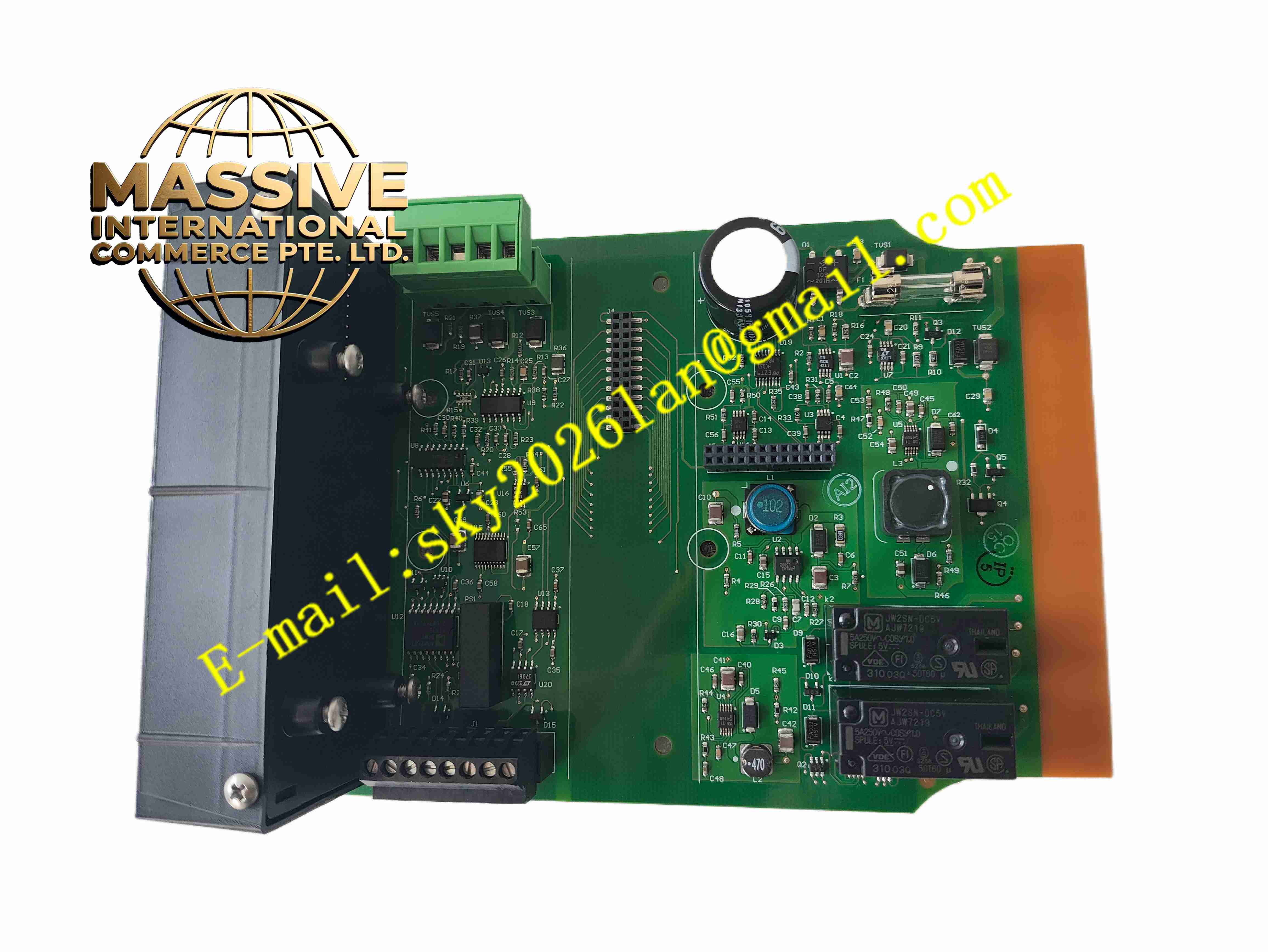
Description
ALSTOM EPSD-0603 / DFI-150-0003
Technical Specifications:
- Power Supply: 24 VDC, 18–36 VDC wide input range
- Input Signal Type: UV, IR, ion current and visible light flame sensor signals
- Sampling Rate: Up to 100 Hz flame signal sampling
- Digital Input: 8 channels TTL/CMOS digital input
- Relay Output: Multi-channel dry contact relay outputs for flame alarm and trip
- Communication: RS485 Modbus RTU
- Operating Temperature: -20 °C to +60 °C
- Storage Temperature: -40 °C to +85 °C
- Isolation: Galvanic isolation between flame sensor input and backplane circuit
Function Features:
- Real time flame signal waveform analysis and flame strength calculation
- Low false alarm rate flame presence and flame loss judgment algorithm
- Multi-type flame sensor signal compatibility
- Built-in sensor cable break and short circuit fault diagnosis
- Configurable flame on / flame off delay time for protection logic
- Relay contact output for hardwired boiler trip interlock
- Transmit flame strength and fault status to DCS via Modbus RTU
- LED indicators for flame status, power and board fault
Application Scenarios:
- Fossil power plant boiler flame safety monitoring system
- Gas turbine burner flame detection rack
- Waste incinerator combustion monitoring cabinet
- Petrochemical process furnace flame protection system
- Retrofit spare parts for Alstom legacy boiler protection control racks
Material Composition:
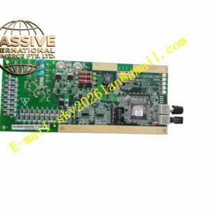
- Substrate: Multilayer FR4 fiberglass printed circuit board with conformal coating
- Core Components: High speed signal operational amplifiers, analog-to-digital converter, industrial microcontroller
- Relays: Safety rated electromechanical relays for trip and alarm outputs
- Connectors: Gold-plated edge connector for rack backplane
- Passive Components: High precision resistors, capacitors and surge suppression diodes
Structural Features:
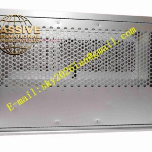
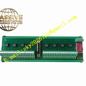
- Standard plug-in Eurocard board form factor for rack chassis installation
- Gold-plated edge connector on rear side for backplane power and signal
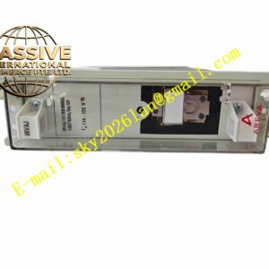
- Front panel with LED status indicators and module label
- PCB surface protected by transparent conformal coating against moisture and dust
- Plastic locking latch for secure insertion and extraction
Working Principle: Flame sensor converts combustion light or ion current into analog electrical signal and sends to EPSD-0603 board. Onboard circuit amplifies, filters and samples flame signal. Microcontroller analyzes signal amplitude and frequency spectrum to judge flame existence. When flame signal drops below threshold longer than preset delay, the board activates flame loss relay output to trigger boiler trip logic. All flame status and fault information is transmitted to upper DCS system through Modbus communication.
Installation Requirements:
- Insert module into matched Alstom flame monitor rack chassis
- Wear anti-static wristband during handling and replacement
- Use shielded cable for flame sensor signal wiring
- Separate flame sensor low voltage signal cable from high voltage power cables
- Verify backplane connector cleanliness before module insertion
- Complete rack protective grounding
Usage Notes:
- Configure flame threshold and flame loss delay parameters before boiler commissioning
- Perform flame simulation test during plant outage to verify trip function
- Inspect gold-plated edge connectors for dust and corrosion periodically
- Disconnect rack power before inserting or removing module
- Do not apply overvoltage to flame sensor input terminals
- Check conformal coating integrity during maintenance inspection