Description
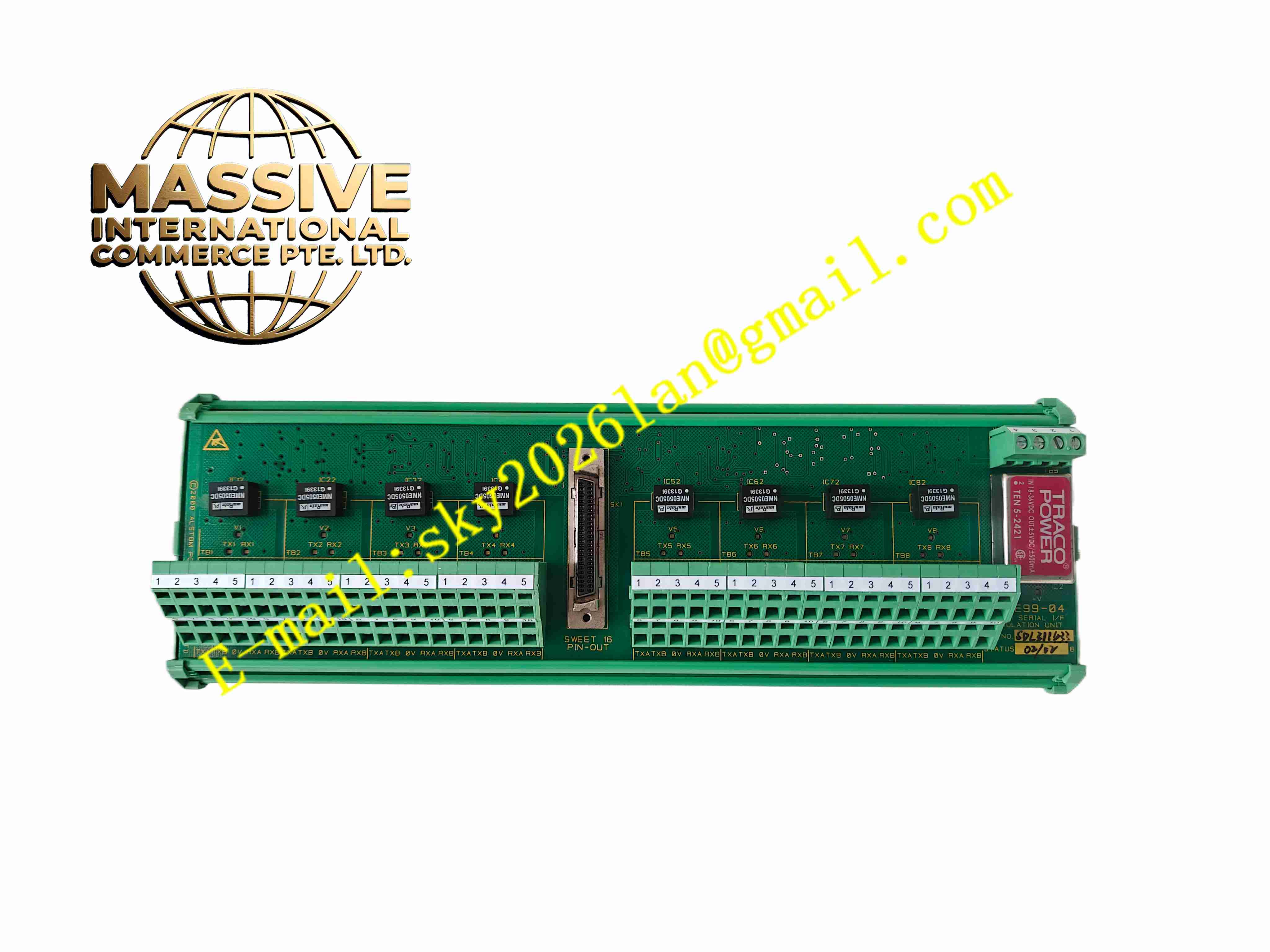
ALSTOM MAE99-04
Technical Specifications
- Product type: Analog output board
- Output channels: 4 × 4 to 20 mA
- Load capability: Max 750 Ω
- Output accuracy: 0.5 % FS
- Supply: Device internal DC24V
- Isolation: Output isolated from device internals
- Temperature: -10 °C to +55 °C
- Storage: -25 °C to +70 °C
- Humidity: 5 % to 95 %, non-condensing
- Protection: IP20
- Installation: Internal plug-in
- Response time: 100 ms
Functional Features
- 4-channel 4 to 20 mA analog output
- External recorder drive of protection measurements
- Output loop wire-break detection
- Output isolated from device internals
- On-board LEDs per channel
- Channel span software configurable
- Board-to-board communication with CPU
- Industrial-grade components
- Substation EMI environment
- Modular plug-in
Application Scenarios
- Substation protection device analog output
- Plant protection measurement remote transmission
- Recorder and indicator drive
- Power fault recorder external output
- Substation integrated automation analog output
Materials and Construction
- PCB: FR4 board
- Output: High-precision DAC, V/I circuit
- Isolation: Optocouplers
- Connector: Board-to-board
- Terminals: Screw-fastened terminals
- Passive components: Metal film resistors, TVS
Structural Features
- Small PCB in protection device analog output slot
- Front panel 4-channel output terminals
- On-board LEDs
- Board-to-board connector to CPU
- No independent housing
- Compact
Working Principle The protection CPU sends 4 to 20 mA setpoints over the board-to-board bus; the DAC converts to voltage, and the V/I circuit produces 4 to 20 mA current to external recorders. Output loop monitoring detects current to identify wire-break. LEDs indicate channel status. Span is configured by software.
Installation Requirements
- Insert output slot with device power off
- Shielded twisted pair output wire
- Do not short output
- Device grounding
- Temperature -10 °C to +55 °C
- Configure output span in device menu after power-up
Precautions
- Insert/remove only with device power off
- Do not short output loop
- Load resistor must not exceed 750 Ω
- Store spares in anti-static packaging
- Calibrate output after software replacement
- Periodically calibrate output accuracy