Description
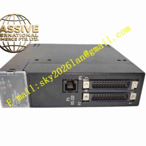
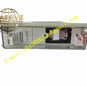
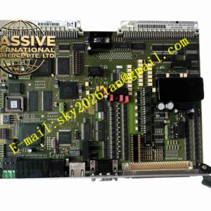
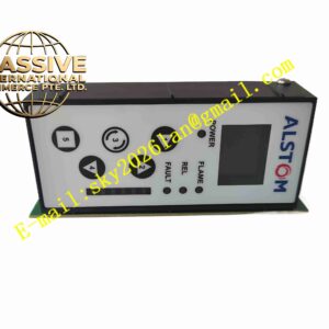
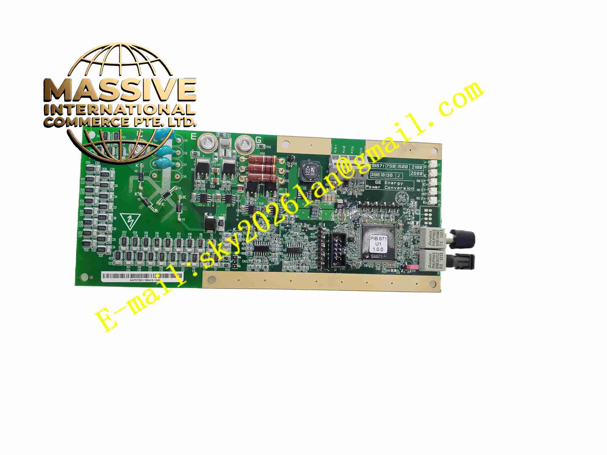
ALSTOM PIB671-1500
Technical Specifications: Product type: DCS rack plug-in power interface board Power input: Rack primary power input Output power: Regulated multi-voltage power supply for rack internal modules Bus interface: Alstom proprietary DCS backplane control bus Voltage monitoring: Built-in multi-channel voltage measurement circuit Operating temperature range:0℃ ~ +60℃ Storage temperature range:-40℃ ~ +85℃ Relative humidity:5% to 95%, non-condensing Mounting form: Single slot plug-in rack board Protection grade:IP20 inside control cabinet
Functional Features: Convert rack input power into multiple stable regulated voltage outputs for DCS control modules. Continuously monitor internal rack supply voltage and trigger alarm when voltage deviates from normal range. Provide galvanic isolation for DCS backplane control bus communication. Front panel LED indicators show power status, bus communication and fault alarm. Power-on self-test checks power regulation circuit and bus communication function. Overvoltage and overcurrent protection for internal power distribution circuit. Backplane bus signal buffering to improve signal integrity across rack slots.
Application Scenarios: Thermal power plant DCS control rack, hydroelectric power unit auxiliary control system, power station boiler and turbine monitoring system, legacy Alstom industrial distributed control cabinet.
Performance Parameters: Stable multi-voltage power output under full rack module load condition. High precision voltage monitoring for rack internal power rail. Bus signal buffer maintains stable communication signal quality along backplane. Continuous long-term stable operation inside air-conditioned power station control cabinet. Protection circuit responds quickly to overvoltage and overcurrent fault.
Material Composition: PCB substrate: Multi-layer FR4 glass fiber epoxy printed circuit board with conformal coating. Core components: Power regulation MOSFET, voltage reference chip, voltage monitoring ADC, bus buffer IC, optocoupler isolation devices, protection fuse components. Front panel: Black flame retardant ABS plastic panel with LED transparent windows. Backplane connector: Gold plated copper alloy edge contact pins.
Structural Features: Single width plug-in rack card design for Alstom DCS chassis. Front panel equipped with multi-color LED indicators for power, bus and fault state. Rear edge gold plated edge connector inserts into rack backplane slot. Internal circuit separated into primary power input zone, power regulation zone, voltage monitoring zone and bus signal buffer zone. Mechanical locking latch fixes board inside rack slot.
Working Principle: PIB671-1500 receives primary power from rack power input terminal after insertion into DCS rack. Power regulation circuit converts input power into multiple stable DC voltage rails for all rack plug-in modules. Voltage monitoring circuit continuously samples each internal power rail voltage value and compares with normal threshold. When voltage exceeds normal range, fault signal is sent to DCS main controller and front panel fault LED is activated. Backplane bus buffer and isolation circuit process control bus signals between main controller and I/O modules. Built-in protection components cut off power output when overvoltage or overcurrent fault occurs.
Installation Requirements: Cut off DCS rack main power before inserting or removing PIB671-1500 board. Insert board into designated rack slot and lock front mechanical latch. Inspect gold plated backplane connector pins for contamination or damage before installation. Power on rack system and execute board power-on self-test. Connect cabinet protective earth to reliable grounding busbar. Reserve air circulation clearance around rack modules for heat dissipation.
Usage Notes: Backup DCS system configuration before board replacement work. Wear anti-static wristband when handling the board. Do not perform hot swap when rack main power is energized. Periodically check front panel LED indicator status and connector cleanliness. Do not operate board outside rated temperature and humidity range. Prevent dust accumulation on backplane gold contact pins.