Description
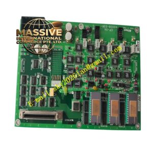
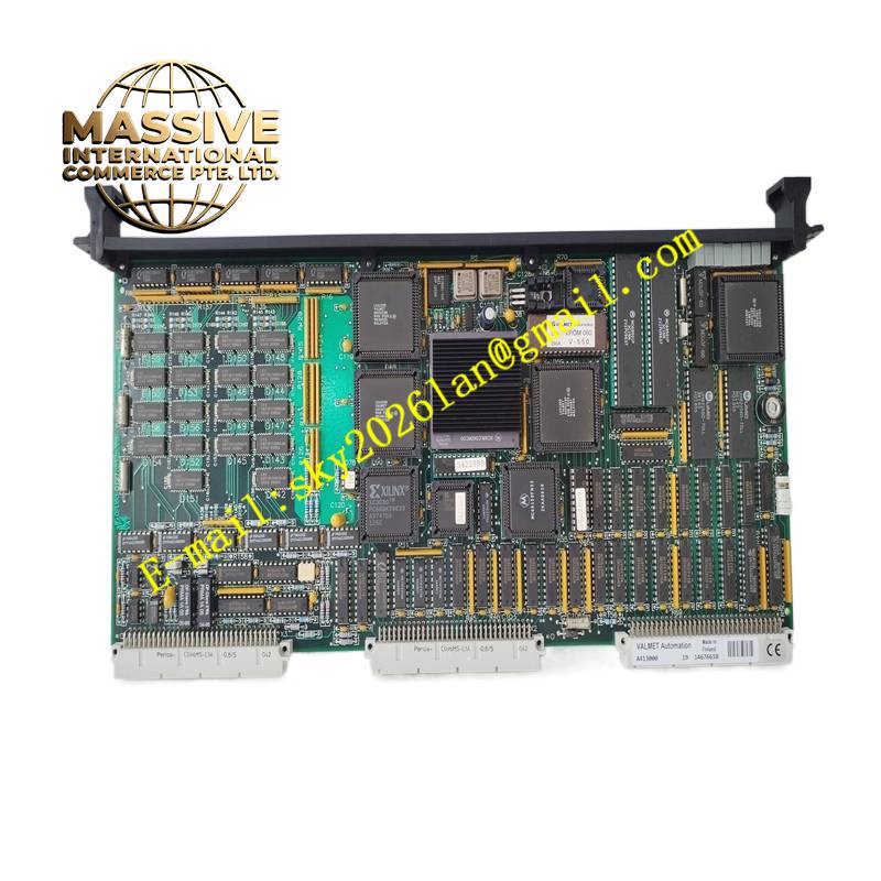
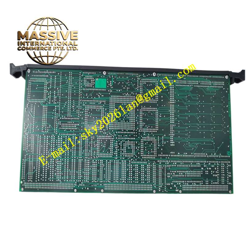
AZUMI A41300
Technical Specifications Mixed digital input and output channels; 24V DC field signal level; channel surge suppression; overcurrent protection for output channels; bus communication interface; DIN rail mounting; channel status LED indicators.
Functional Features Detects open and closed states of field limit switches, pressure switches and proximity sensors. Receives control commands from main controller and switches output channel state to actuate field actuators. Provides hardware overcurrent protection for each output channel. Sends channel diagnostic information, wire break and short-circuit fault codes to the main controller. Supports remote channel enable and disable through system configuration.
Application Scenarios Factory assembly line automation, packaging machine control, water treatment plant discrete control, general industrial machine PLC I/O cabinets.
Performance Parameters Fast discrete signal sampling cycle; high isolation voltage between field side and control logic side; stable bus communication; reliable on-off switching under industrial electromagnetic interference.
Material Composition Module housing uses flame-retardant engineering plastic; internal PCB is FR-4 multilayer board; optocoupler chips provide channel isolation; terminal screws and contact pieces are nickel-plated copper alloy.
Structural Characteristics Rectangular DIN rail mounted unit; upper and lower screw terminal blocks for field wiring; front panel LED indicators for each input and output channel; side bus connector for linking to controller backplane or communication adapter.
Working Principle Field discrete signals pass through optocoupler isolation circuits before entering the module logic chip. The microcontroller samples each input channel cyclically and uploads status data to the main controller via the communication bus. For output channels, the microcontroller receives commands from the controller and drives power switching circuits to change the on-off state of external loads. Built-in monitoring circuits detect overcurrent and short-circuit conditions on output terminals.
Installation Requirements Clip the module onto standard DIN rail inside the control cabinet. Wire field sensors and actuators to corresponding screw terminals following wiring diagrams. Connect the module communication bus to the master controller or adapter. Configure channel types and fault logic in the automation programming software.
Precautions for Use Do not connect AC high-voltage signals directly to 24V DC signal terminals. Tighten terminal screws to prevent loose contact in vibration environments. Keep the module ventilation area free of dust and conductive debris.