Description
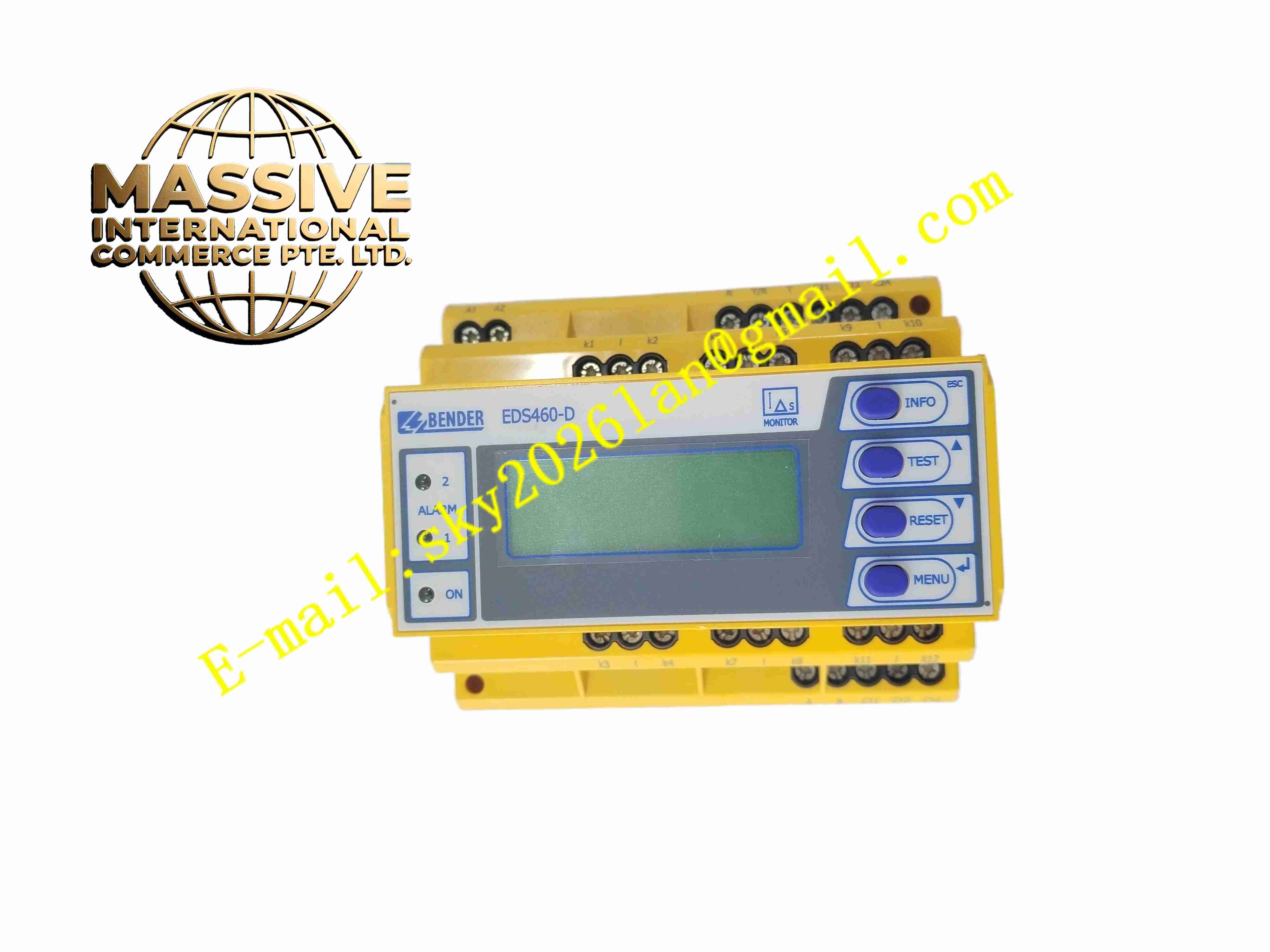
Bender EDS460-D-1
Technical Specifications
- Product Type: Insulation monitoring relay for IT systems
- Monitored System: AC, DC and AC/DC mixed unearthed networks
- Monitoring Voltage Range: 0 V to 690 V
- Measurement Range: 0 kΩ to 999 kΩ insulation resistance
- Alarm Output: Relay contact output for pre-alarm and main alarm
- Communication Interface: Modbus RTU
- Power Supply: 24 VDC
- Protection Rating: IP20
- Operating Temperature: -20 °C to +60 °C
- Certifications: IEC 61557-8, CE, UL
Functional Features
- Continuous measurement of insulation resistance between all live lines and earth in ungrounded IT power systems.
- Two-stage alarm threshold: pre-alarm for early insulation degradation and main alarm for critical fault.
- Integrated automatic self-test function to verify device health periodically.
- Modbus RTU communication transmits real insulation resistance value and fault status to PLC or SCADA.
- Visual LED indicators show normal operation, pre-alarm and fault alarm states.
- Adjustable alarm threshold values to match different system requirements.
- No interference to normal power supply operation during measurement.
- High immunity against conducted and radiated electromagnetic interference.
- Latching or non-latching alarm mode selectable via parameter setting.
- Fault memory stores last earth fault event information.
Application Scenarios
- Medical operating room isolated power supply
- Marine vessel ungrounded power distribution network
- Mining underground IT power systems
- Industrial mobile machinery unearthed power network
- Data center isolated auxiliary power systems
Material Composition
- Housing: Flame-retardant thermoplastic enclosure
- Main PCB: FR4 printed circuit board with conformal coating
- Measuring circuit: High precision measurement resistors and signal processing chips
- Relay components: Sealed micro relays for alarm output
- Terminal block: Copper alloy screw terminals
- LED indicators: High brightness status LEDs
Structural Characteristics
- Standard DIN rail modular rectangular housing.
- Front panel contains LED status indicators and operation buttons for parameter setting.
- Upper terminals connect to monitored power network and earth reference.
- Lower terminals for alarm relay output and Modbus communication wiring.
- Internal high impedance measuring circuit electrically isolated from monitored power system.
- Rear DIN rail locking clip for cabinet mounting.
Working Principle The device injects low-amplitude measuring pulses into the unearthed power network. The measuring circuit calculates insulation resistance value by measuring leakage current between live conductors and earth. When insulation resistance drops below preset threshold, the internal logic triggers relay contact state change and alarm signal. The self-test circuit periodically generates simulated fault signal to verify measurement and alarm function. Modbus bus transmits real resistance value and fault event data to upper monitoring system.
Installation Requirements
- Mount on DIN rail inside electrical cabinet.
- Connect measuring terminals to all live conductors of IT power system.
- Use dedicated earth reference connection for measurement reference.
- Route communication wiring with shielded twisted pair cable.
- Set alarm thresholds according to local electrical safety standards.
- Perform manual self-test after installation to validate alarm function.
- Keep measuring wiring separated from high-current power cables.
Usage Notes
- The device only applies to unearthed IT power systems, not for earthed TN or TT systems.
- Do not touch live measuring terminals when power network is energized.
- Periodically execute self-test function to verify device functionality.
- Remove parallel insulation monitoring devices on same network to avoid measurement conflict.
- Do not modify internal circuit components.
- Check terminal tightness during routine maintenance.
- Reset fault memory after earth fault troubleshooting completes.