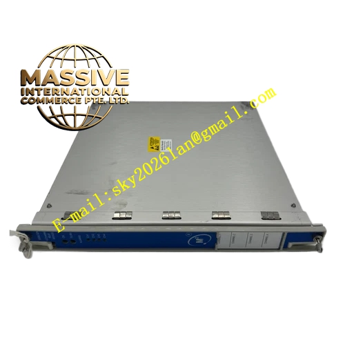
Description
Bently 128031‑01
Technical Specifications:
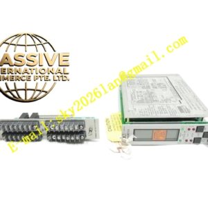
- Form Factor: Rear‑slot matching module for 3500 rack, mates with front full‑height monitor module
- Input Channel Quantity: 4 sensor input channels, corresponding one‑to‑one with front monitor module channels
- Supported Sensor Type: Eddy‑current proximity probes, seismic velocity transducers, piezoelectric acceleration sensors
- Termination Type: Internal direct screw‑screw terminal termination
- Terminal Block: Removable green spring‑screw terminal blocks
- Operating Temperature: ‑30 °C ~ +65 °C
- Storage Temperature: ‑40 °C ~ +85 °C
- Relative Humidity: 5%‑95% RH non‑condensing
- Weight: 0.22 kg
- Compatibility: Matches 3500/42E, 3500/44, 3500/44M front‑slot monitor modules Functional Features:
- Internal direct‑termination design eliminates external intermediate termination hardware, reduces quantity of signal‑cable connectors and potential failure points.
- Four‑channel full‑correspondence signal‑wiring interface for proximity and seismic sensor signals.
- Removable terminal‑block structure permits pre‑wiring outside rack cabinet for convenient commissioning and maintenance work.
- Strict mechanical‑position interlock, only install into rear slot aligned with matched front‑slot monitor module.
- Conducts raw sensor signal through rack internal back‑plane directly to front‑monitor‑module circuit without external signal‑cable transition.
- Compact rear‑slot structure occupies no additional cabinet installation space beyond original 3500 rack footprint. Application Scenarios: 3500 rack machinery‑protection system cabinet‑internal wiring; turbine and compressor TSI system integration project; projects requiring reduction of external intermediate wiring connections; replacement‑upgrade for old external‑termination I/O assemblies. Performance Parameters: Low‑signal‑path impedance; high signal‑integrity transmission for low‑level sensor signals; stable electrical‑contact performance under long‑term cabinet vibration environment. Material Composition: Multi‑layer signal‑transmission PCB; gold‑plated back‑plane contact pins; high‑reliability removable screw terminal‑block assembly; reinforced engineering‑plastic housing structure. Structural Characteristics: Slim rear‑slot module physical dimension; row‑arranged multi‑channel removable terminal blocks on module front‑face; rear gold‑plated contact pins insert into 3500 rack rear‑back‑plane; mechanical locating tabs guarantee correct slot‑position installation. Working Principle: Field sensor signal wires terminate onto module removable terminal blocks. PCB traces route sensor signals to rear gold‑plated contact pins. Rack rear‑back‑plane transmits raw analog sensor signals to corresponding front‑slot monitor module input circuit. No signal conditioning or signal‑processing circuit resides inside this I/O termination module; it purely implements physical‑signal‑routing function. Installation Requirements:
- Power‑off 3500 rack before installing or removing this rear‑slot I/O module. Hot‑swap operation is not supported for 128031‑01.
- Insert module strictly into rear slot position aligned with target front‑slot monitor module. Mechanical locating tabs prevent mis‑slot installation.
- Strip sensor‑cable insulation to specified length, fasten each conductor firmly onto corresponding channel terminal screw, avoid loose strands causing short‑circuit risk.
- After wiring completion, insert terminal‑block fully back into module body, confirm positive locking engagement.
- Double‑check channel‑to‑sensor correspondence to prevent cross‑channel mis‑wiring. Usage Notes:
- Never perform hot‑plug under rack powered condition; power‑off rack before module removal or insertion.
- Keep terminal‑block screw torque within specified range; over‑tightening damages terminal‑block internal spring structure, under‑tightening creates high‑resistance loose‑contact points.
- Prevent metal wire debris from falling into module housing; conductive debris creates signal short‑circuit faults.
- Module implements pure signal‑routing function; signal‑fault events shall be diagnosed from front‑slot monitor‑module status indicators, not from this rear‑termination module.