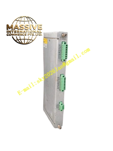
Description
Bently 131178‑01
- Key Features: Screw‑type terminal block design for field wiring; electrical isolation between rack internal circuit and field side; mechanical locking structure for rack installation; supports multi‑channel signal termination; dust‑resistant housing structure; compatible with multiple 3500 monitor variants; simplifies field maintenance and troubleshooting.
- Technical Specifications & Performance Parameters
- Operating temperature: 0 ℃ ~ +60 ℃
- Storage temperature: ‑40 ℃ ~ +85 ℃
- Terminal rated voltage: 300 V
- Terminal rated current: 2 A per channel
- Insulation resistance: ≥100 MΩ
- Weight: 0.31 kg
- Material Composition: FR‑4 fire‑retardant printed circuit substrate; tin‑plated copper screw terminal blocks; glass‑filled nylon insulating housing; gold‑plated male edge connector; high‑strength glass‑reinforced plastic locking latch.
- Structural Features: Compact plug‑in mechanical structure matching 3500 rack slot; row‑arranged screw terminals on front‑facing side; rear‑mount gold‑plated edge connector mating with corresponding monitor module; integrated mechanical lock tab preventing loose disconnection; internal isolating barrier separating rack circuit and field wiring area.
- Working Principle: It serves as passive signal transfer medium. Field sensor analog signals enter via screw terminals, route through internal PCB traces, and transmit to paired monitor module through edge connector. It provides physical wiring access point without modifying internal monitor circuit.
- Application Scenarios: Field signal termination for proximity probes, velocity sensors and keyphasor sensors in 3500 TSI racks; petrochemical compressor and steam‑turbine monitoring system field wiring interface; spare‑part replacement for existing 3500 rack termination assemblies; on‑site maintenance wiring access for machinery protection systems.
- Installation Requirements: Align module and insert into dedicated slot directly behind corresponding monitor module; fully engage mechanical locking latch; torque each field‑wiring screw terminal to factory‑specified torque value; separate low‑level sensor signal cables away from high‑voltage power cables; tighten cable gland fittings to avoid cable pull stress on terminals.
- Usage Notes: Do not apply excessive torque on screw terminals to prevent terminal block damage; strictly prohibit mixing high‑power circuit wiring with low‑level sensor signal terminals; inspect terminal screw tightness during every equipment overhaul; avoid conductive dust accumulation on terminal block surfaces.