Description
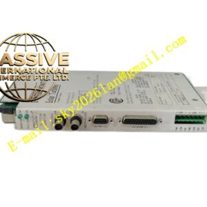
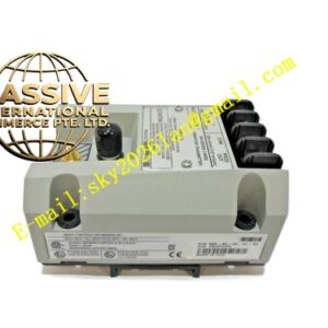
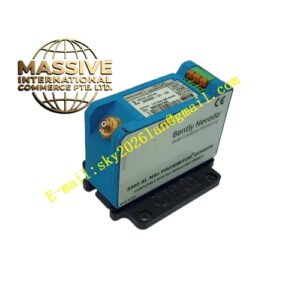
Bently 132417‑01 (190662‑26)
- Key Features: Separable I/O module and shielded communication cable assembly; multi‑protocol signal transmission support; noise‑suppressing full‑coverage shielding; reliable mechanical locking connectors; hot‑swap compatible; consistent impedance matching for industrial communication signal.
- Technical Specifications & Performance Parameters
- I/O module operating temperature: 0 ℃ ~ +60 ℃
- Cable operating temperature: ‑51 ℃ ~ +85 ℃
- Storage temperature: ‑40 ℃ ~ +90 ℃
- Communication cable impedance: 120 Ω nominal
- Weight: 0.44 kg total assembly
- Material Composition: FR‑4 multilayer PCB for I/O unit; tin‑plated screw terminals; high‑purity twisted‑pair copper conductors inside cable; double‑layer copper braided shielding; FEP fluoropolymer cable insulation; metal‑shell D‑sub connectors with locking screws.
- Structural Features: Plug‑in rack‑mount I/O module structure; screw‑type termination terminals on I/O module front side; shielded twisted‑pair cable with metal D‑sub connectors on both ends; locking screw hardware for connector anti‑loosening; continuous full‑length shielding layer running entire cable length.
- Working Principle: Rack internal communication bus signal passes from 3500/92 gateway module backplane edge connector into I/O termination module. Signals route to screw terminals and transfer onto matched shielded 190662‑26 communication cable assembly. Cable transmits protocol‑encoded data to external DCS, PLC or configuration workstation. Double‑layer shielding suppresses external electromagnetic interference.
- Application Scenarios: Physical communication wiring for 3500/92 gateway module; data link between 3500 TSI rack and plant‑wide DCS control system; connection to 3500 rack configuration software host computer; petrochemical and power‑plant turbomachinery monitoring‑system communication interface.
- Installation Requirements: Insert I/O module into dedicated slot behind 3500/92 gateway module; fasten mechanical latch; secure each field‑wiring terminal screw with proper torque; attach D‑sub connectors on both cable ends and fully tighten locking screws; route communication cable in separate cable tray isolated from high‑power power cables; implement single‑end shielding grounding.
- Usage Notes: Do not cut, splice or shorten 190662‑26 factory‑assembled communication cable assembly; maintain minimum cable bending radius; avoid mechanical crushing or squeezing on cable jacket; inspect D‑sub connector pin integrity during overhaul cycles; prevent oil mist and moisture contamination on connector contact surfaces.