Description
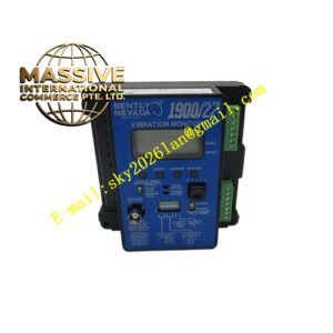
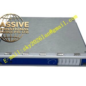
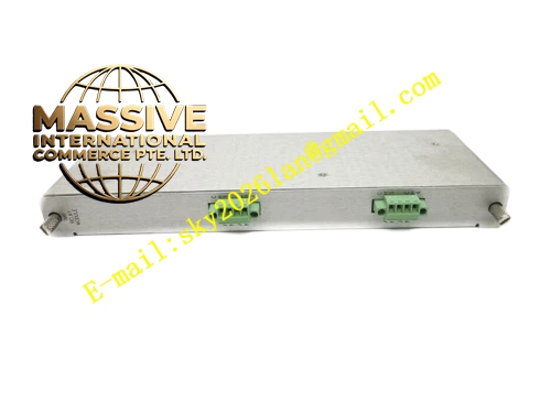
Bently 132419‑01 (190662‑28)
- Key Features: Enhanced double‑shielded communication cable assembly; improved anti‑interference performance for heavy‑EMI industrial sites; D‑sub locking‑connector mechanical retention; screw‑terminal field‑wiring interface; fully hot‑swap compatible; supports Modbus‑RTU, Modbus‑TCP and other standard industrial protocols.
- Technical Specifications & Performance Parameters
- I/O module operating temperature: 0 ℃ ~ +60 ℃
- Cable operating temperature: ‑51 ℃ ~ +85 ℃
- Storage temperature: ‑40 ℃ ~ +90 ℃
- Nominal cable characteristic impedance: 120 Ω
- Weight: 0.47 kg total assembly
- Material Composition: FR‑4 industrial‑grade printed circuit board; tin‑plated copper screw terminals; high‑purity twisted‑pair copper conductors; double‑layer copper braid plus foil composite shielding; FEP high‑temperature insulation material; nickel‑plated metal D‑sub connector shells.
- Structural Features: Plug‑in rack‑mount I/O module form factor; front‑facing screw‑terminal wiring points; rear‑side gold‑plated edge connector for rack‑backplane mating; enhanced‑spec double‑shielded communication cable with metal D‑sub connectors at both ends; built‑in strain‑relief reinforcement at cable‑connector transition sections.
- Working Principle: Digital communication data from 3500/92 gateway module passes through rack backplane into 132419‑01 I/O module. Signal transfers onto 190662‑28 enhanced double‑shielded communication cable assembly. Composite‑shield cable suppresses high‑level electromagnetic noise from large‑motors and variable‑frequency drives, delivering stable protocol‑data stream to upper‑level automation host equipment.
- Application Scenarios: Communication wiring for 3500/92 gateway module inside high‑EMI industrial workshops; connection between 3500 machinery‑protection rack and plant DCS/SCADA; spare‑part replacement for enhanced‑noise‑environment communication loops; power‑plant gas‑turbine and steam‑turbine monitoring‑system data‑transmission link.
- Installation Requirements: Install I/O module directly behind corresponding 3500/92 gateway module; engage mechanical locking latch; tighten each screw‑terminal field‑wiring point to specified torque; mount D‑sub connectors and fully fasten locking screws; route communication cable inside independent cable‑tray separated from high‑power‑cable routes; configure single‑point shielding grounding mode.
- Usage Notes: Forbid field cutting or splicing of factory‑integrated 190662‑28 communication cable; strictly follow minimum cable bending‑radius requirement; prevent mechanical impact to D‑sub connector pins; inspect connector contact cleanliness during periodic overhaul; avoid long‑term exposure of cable assembly to direct high‑temperature radiation.