Description
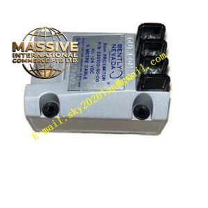
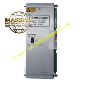
Bently 19000‑00‑95‑12‑02
- Technical Specifications
- Input type: Eddy‑current probe, IEPE accelerometer, tachometer, 4‑20 mA process signal
- Dynamic signal frequency bandwidth: 0.2 Hz up to 20 kHz
- Sampling architecture: Multi‑channel synchronous high‑speed sampling
- Interfaces: RS‑485 Modbus RTU, 10/100 Mbps Ethernet
- Power supply: 24 VDC, typical power consumption approx 15 W
- Operating temperature range: ‑25 °C ~ +70 °C
- Enclosure: Rack‑mount or panel‑mount metal housing
- Certifications: CE, UL, ATEX for hazardous industrial installation
- Functional Features: Simultaneous multi‑channel synchronous sampling preserves phase relation across vibration signals. Supports waveform capture, FFT spectrum generation, amplitude trend calculation. Configurable voting logic prevents false alarms caused by single‑channel noise disturbance. Internal large‑capacity event buffer stores alarm snapshots, fault logs and machine transient data. Seamless interoperability with host monitoring software for remote diagnostic review. Heavy‑duty surge and transient suppression circuit improves performance under noisy plant electrical environment. Time‑synchronisation capability for correlating machine events across multiple monitoring modules.
- Application Scenarios: Critical assets including large steam turbines, centrifugal compressors, turbo‑generators, heavy‑duty process blowers. Applied in petrochemical complexes, energy generation plants, metallurgical processing facilities. Used as front‑end data acquisition hardware for online predictive‑maintenance systems; supplies both protection‑level alarm signals and high‑resolution diagnostic vibration data.
- Performance Parameters: High sampling rate ensures accurate capture of rotor dynamic events. Synchronised sampling keeps correct phase information for orbit and polar‑plot analysis. Non‑volatile memory retains configuration and historical log data upon power loss. Diagnostic functions detect sensor fault, signal overload and wiring failure.
- Material Composition: Robust painted metal enclosure to resist cabinet‑side mechanical impact. Industrial multi‑layer PCB integrated with transient‑protection components. High‑reliability spring‑loaded screw terminals for field wiring connection.
- Structural Characteristics: Modular rack‑mount construction. Front panel status LED indicators for power, communication status and channel alarm status. Separate terminal groups allocated for sensor input, tachometer, relay output, power supply and network port. Internal circuit layout separates low‑level analogue section and digital communication section to reduce noise coupling.
- Working Principle: Vibration, displacement and speed analogue signals from field sensors enter signal‑conditioning circuits. Anti‑aliasing filters clean input waveforms before high‑speed analogue‑digital conversion. Digital processor performs amplitude computation, FFT frequency‑domain transformation and threshold comparison. When measurement breaches configured set‑points, alarm status updates and relay outputs respond. Raw and processed data packaged for transmission over Modbus or Ethernet to upper‑level systems. Fault‑diagnostic algorithms continuously watch signal quality for sensor or wiring defects.
- Installation Requirements: Install inside climate‑controlled instrument cabinet. All sensor wiring must use shielded twisted‑pair cable. Physically separate low‑amplitude sensor wiring from high‑voltage power cables. When deployed within explosive classified zones strictly follow local hazardous‑area installation codes. Ensure cabinet protective earth connection is properly implemented. Provide adequate ventilation around module for heat dissipation.
- Usage Notes: Do not exceed maximum allowable input signal amplitude, signal overload can damage internal circuits. Monitor 24 VDC power quality; large voltage fluctuation may trigger unexpected fault status. Under high‑vibration cabinet environment, regularly check terminal screw tightness to avoid loose connections. Respect manufacturer recommended recalibration cycle. Never open metal housing in field; internal components are not field‑serviceable.