Description
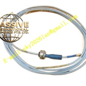
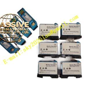
Bently 190501‑00‑00‑00
- Technical Specifications
- Sensing principle: Piezoelectric acceleration with on‑board analogue integration to velocity
- Nominal Sensitivity: 3.94 mV/mm/s (100 mV/in/s), tolerance ±5 % factory calibrated
- Frequency Response: 3 Hz‑900 Hz (±1 dB); 1.5 Hz‑1000 Hz (±3 dB)
- Maximum measurable velocity: 63.5 mm/s peak
- Excitation power requirement: 9‑36 VDC loop power; maximum consumption 5 mA
- Operating temperature: ‑40 °C ~ +85 °C
- Storage temperature: ‑55 °C ~ +100 °C
- Maximum cable length: 305 m (1000 ft)
- Electrical connector: 2‑pin 316L stainless steel military‑style hermetic connector
- Housing material: 316L stainless steel
- Functional Features: Superior low‑frequency performance tailored for slow‑speed fans. Signal conditioning circuit fully encapsulated within sensor body, avoids external integration hardware requirement. Hermetically sealed stainless‑steel housing resists outdoor moisture, salt‑spray and chemical vapour. Loop‑powered two‑wire connection simplifies field wiring. Output signal can feed general‑purpose 4‑20 mA monitors or Bently dedicated vibration monitors. Shock‑resistant mechanical design withstands fan‑plant continuous heavy vibration. Hazardous‑area certification permits mounting in explosive atmosphere locations.
- Application Scenarios: Cooling tower axial fan assemblies, air‑cooled condenser fans, low‑speed gearboxes for large fans, slow‑speed induced draft fans. Widely used in power‑plant cooling islands, petrochemical plant air‑cooler facilities. Outdoor casing vibration measurement under harsh weather conditions.
- Performance Parameters: Excellent amplitude linearity within full measuring range. Seismic mass piezoelectric element delivers stable output at low rotational speed. Output impedance well matched for long cable runs. Built‑in overload protection prevents damage under excessive vibration shock.
- Material Composition: 316L stainless‑steel hermetically sealed housing. Internal high‑sensitivity piezoelectric crystal sensing element. Precision seismic mass. On‑board encapsulated analogue integration circuit. All internal assemblies fully sealed against moisture ingress.
- Structural Characteristics: Compact cylindrical threaded‑body construction. Two‑pin military‑spec connector located on top face. External mounting thread at base for direct installation onto equipment casing. Fully welded hermetic housing with no vent holes.
- Working Principle: External casing vibration applies force onto internal seismic mass. Piezoelectric crystal generates charge proportional to acceleration. The built‑in analogue integration circuit converts acceleration signal into velocity‑proportional voltage output. The transducer requires external 9‑36 VDC loop power for internal circuit operation. Output voltage varies linearly with machinery casing vibration velocity.
- Installation Requirements: Mount onto rigid flat section of fan housing or gearbox casing. Remove thick paint, coating and rust from mounting surface to achieve full metal‑to‑metal contact. Sensor sensitive axis must align with target vibration direction. Use shielded twisted‑pair field cable. For outdoor installation avoid permanent direct solar radiation where practical. Secure connector to prevent water ingress. Do not apply excessive torque onto sensor housing during mounting.
- Usage Notes: Prevent heavy mechanical impact during transportation and installation. Always maintain supply voltage strictly between 9 VDC‑36 VDC. Never exceed maximum measurable peak velocity value. Inspect connector sealing condition periodically in humid outdoor environment. Avoid applying pulling stress directly onto sensor connector; support cable weight separately.