Description
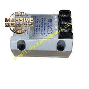
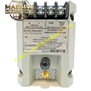
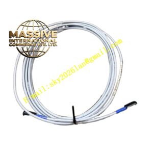
Bently 330907-05-30-10-02-05
Technical Specifications
- Product Series: 3300 XL 11mm Eddy Current Sensor System
- Probe Diameter: 11 mm (0.43 inches)
- Sensitivity: 100 mV/mil (3.94 V/mm) ± 6.5%
- Thread Specification: M14 x 1.5 Metric Thread
- System Length: 3.0 meters (10 feet) total system length
Functional Features
- Extended Linear Range: Offers a wider linear operating range (up to 110 mils / 2.8 mm), ideal for machinery with larger shaft runout or clearance variations.
- High Energy Output: Generates a stronger signal, providing excellent signal-to-noise ratio in challenging environments.
- System Interchangeability: Fully interchangeable with other 3300 XL 11mm components without individual calibration.
Application Scenarios
Perfectly suited for large turbines, heavy-duty compressors, and industrial fans where shaft displacements are significant and a wider linear range is required to prevent signal saturation.
Performance Parameters
- Linear Measurement Range: 110 mils (2.8 mm)
- Frequency Response: 0 to 10 kHz (-3 dB)
- Operating Temperature Range: -52°C to +177°C (-62°F to +350°F)
- Supply Voltage: -24 VDC nominal
Material Composition
Constructed with premium 316L stainless steel and high-temperature dielectric materials, ensuring structural integrity and electrical isolation in demanding environments.
Structural Characteristics
Features a streamlined profile with an integrated cable exit that minimizes bending stress. The M14 thread provides secure mounting in heavy machinery housings.
Working Principle
Operates on the principle of electromagnetic induction. The probe acts as one plate of a transformer, with the conductive shaft acting as a shorted secondary. Changes in gap alter the coupling coefficient, changing the coil’s impedance.
Installation Requirements
Install in a properly sized M14 tapped hole. Ensure adequate clearance around the probe body to prevent electrical arcing to grounded surfaces. Verify that the total system length matches the proximitor’s calibration specification.
Usage Precautions
Inspect the probe tip for scratches or pitting before installation, as surface damage can cause signal non-linearity. Keep the cable away from sharp edges and hot exhaust pipes.