Description
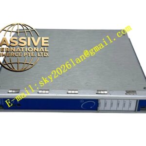
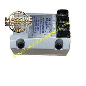
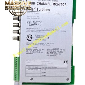
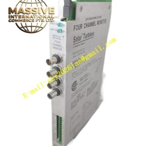
Bently 3500/22‑01‑01‑00 (146031‑01)
- Key Features: Real‑time acquisition of steady‑state and high‑speed transient waveform data; built‑in 10/100 Base‑TX Ethernet communication port; supports large‑capacity rotor‑orbit, 1X/2X vector and time‑waveform data transmission; bidirectional communication with 3500 rack configuration software; supports connection to multiple M‑series monitor modules; complete hot‑swap capability; front‑panel multi‑color LED status indicators; supports timestamp for all transient‑data frames.
- Technical Specifications & Performance Parameters
- Typical power consumption: 7.5 W
- Operating temperature: ‑30 ℃ ~ +65 ℃
- Storage temperature: ‑40 ℃ ~ +85 ℃
- Communication interface: 10 / 100 Mbps auto‑negotiation Ethernet RJ45
- Humidity tolerance: 5 %‑95 % non‑condensing
- Weight: 0.40 kg
- Material Composition: FR‑4 multilayer industrial printed‑circuit board; high‑speed data‑processing microprocessor chip; magnetic isolation components for Ethernet signal circuit; gold‑plated back‑plane edge connector; metal front‑panel equipped with multi‑color LED indicators; RJ45 Ethernet metal shielded connector; reinforced plastic mechanical locking latch.
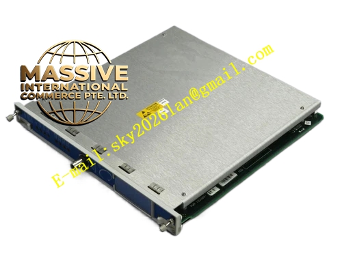
- Structural Features: Full‑height plug‑in rack‑module mechanical form factor; front‑panel LED indicators display power‑supply, rack‑bus communication and Ethernet link status; rear‑side gold‑plated edge connector mates with 3500 rack back‑plane bus; 146031‑01 I/O unit integrates RJ45 Ethernet port and auxiliary screw‑termination signal terminals; mechanical locking latch fastens module inside rack slot.
- Working Principle: TDI module continuously communicates with every monitor module through rack internal back‑plane bus, collects static measurement values, high‑speed sampled waveform blocks, rotor orbit data and fault event records. Module packages raw diagnostic data into standard Ethernet protocol frames, transmits data stream to remote System 1 workstation. It also receives configuration command and data‑acquisition trigger instruction from host software and forwards commands onto rack back‑plane bus to control all monitor modules.
- Application Scenarios: High‑volume transient‑diagnostic‑data gateway for steam‑turbine, gas‑turbine and centrifugal‑compressor 3500 racks; data link between 3500 machinery‑protection rack and System 1 fault‑diagnosis workstation; turbomachinery rotor‑orbit and vibration‑vector on‑line analysis; petrochemical and power‑plant rotating‑machinery predictive‑maintenance monitoring system.
- Installation Requirements: Insert full‑height TDI module into designated rack slot behind monitor modules; fully engage mechanical locking latch; connect Ethernet communication cable to RJ45 port on I/O assembly; configure IP address, subnet mask and data‑acquisition parameters in 3500 rack configuration software; verify Ethernet link status via front‑panel LED indicators after power‑on.
- Usage Notes: Apply ESD static‑protection measures when handling module hardware; strictly follow official maintenance manual for hot‑swap execution; use shielded industrial‑grade Ethernet cable for long‑distance network wiring; isolate TDI Ethernet network from office‑level IT local area network; save rack‑configuration backup file after modifying network‑related parameters.