Description
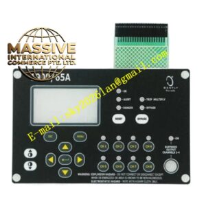
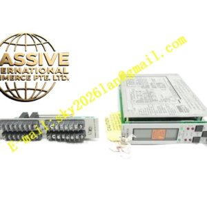
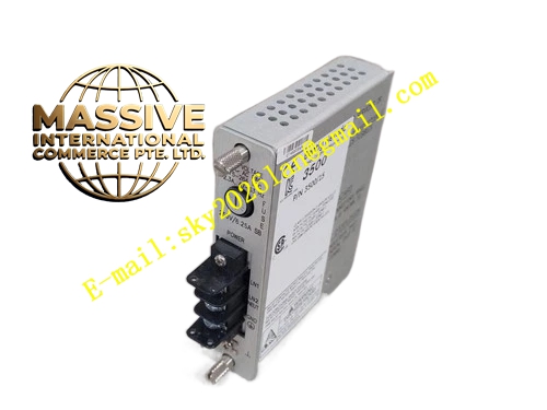
Bently 3500/25‑01‑03‑00 (135473‑01)
- Key Features: Two independent keyphasor‑input channels; compatible with proximity‑probe and magnetic‑pickup‑sensor‑input sources; configurable trigger‑threshold‑parameters; generates digital once‑per‑revolution timing‑pulse; supplies rotational‑speed and phase‑reference for vibration‑vector‑and‑rotor‑orbit‑calculation; external‑termination‑design requiring matched I/O‑module; hot‑swap maintainability.
- Technical Specifications & Performance Parameters
- Input channel quantity: 2 independent keyphasor‑input channels
- Maximum measurable rotational‑speed: 200 000 RPM
- Typical power consumption: 4.4 W
- Operating temperature: 0 ℃ ~ +60 ℃
- Storage temperature: ‑40 ℃ ~ +85 ℃
- Weight: 0.30 kg
- Material Composition: FR‑4 multilayer printed‑circuit‑board; high‑speed timing‑processing‑chip; trigger‑threshold‑adjustment‑circuit‑components; gold‑plated back‑plane edge‑connector; metal front‑panel fitted with multi‑color LED‑status‑indicators; external‑termination‑matching‑circuit‑components; reinforced‑plastic mechanical‑locking‑latch.
- Structural Features: Half‑height plug‑in rack‑module mechanical‑structure; front‑panel LED‑indicators for power‑supply‑status and keyphasor‑signal‑presence; rear‑side gold‑plated edge‑connector mates with rack‑back‑plane bus; field‑sensor‑wiring connects to separate matched external‑I/O‑termination‑module; mechanical‑locking‑latch secures module‑position inside rack‑slot.
- Working Principle: Analog trigger‑signal from field‑mounted keyphasor‑sensor enters system via matched external‑I/O‑termination‑module. Module internal‑circuit detects shaft‑notch or gear‑tooth passing‑event according to user‑configured trigger‑threshold‑setting. It generates standardized digital keyphasor‑timing‑pulse and calculates real‑time shaft‑rotational‑speed value. Timing‑pulse and speed‑value broadcast onto rack‑back‑plane bus for all monitor‑modules. Monitor‑modules utilize timing‑reference to compute vibration‑phase‑angle, 1X‑amplitude and rotor‑orbit‑data.
- Application Scenarios: Phase‑reference‑and‑speed‑measurement for steam‑turbine and centrifugal‑compressor units; rotor‑orbit‑and‑vibration‑vector‑calculation for rotating‑machinery‑fault‑diagnosis; 3500‑rack‑speed‑protection‑function‑implementation; petrochemical‑and‑power‑plant TSI‑systems adopting external‑termination‑wiring‑architecture.
- Installation Requirements: Insert half‑height keyphasor‑module into designated rack‑slot; fully engage mechanical‑locking‑latch; install corresponding matched external‑I/O‑termination‑module and complete field‑keyphasor‑sensor‑wiring; configure trigger‑threshold‑voltage and sensor‑type‑parameter inside rack‑configuration‑software; perform shaft‑barring‑test to verify keyphasor‑pulse‑generation and rotational‑speed‑reading‑accuracy.
- Usage Notes: Apply ESD static‑electric‑protection‑measures during module‑handling and replacement; avoid unauthorized hot‑swap‑operation; inspect front‑panel‑signal‑LED‑status during daily‑equipment‑inspection‑rounds; adjust trigger‑threshold‑value matching actual‑shaft‑notch‑geometric‑characteristic; preserve complete rack‑configuration‑backup‑file after finishing‑parameter‑modification‑operations.