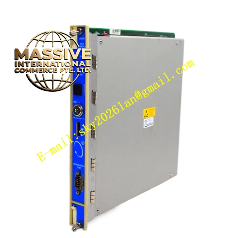
Description
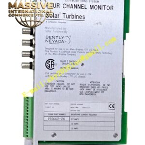
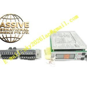
Bently 3500/32 149986-02
Technical Specifications
- Module Type: 4-Channel Relay Control Module
- Front Panel Assembly: 149986-02
- Channel Count: 4 independent relay outputs
- Slot Placement: Can be placed in any available slot on the right side of the Transient Data Interface (TDI) module
Functional Features
- Independent Programming: Each of the four outputs can be independently programmed to execute specific voting logic.
- Flexible Logic: Supports AND and OR logic programming using alarm inputs (Alert and Danger states), Non-OK status, or separate PPLs from any monitoring channel in the rack.
- Fail-Safe Design: Relays are normally energized; loss of power or module failure de-energizes the relay to a safe state.
Application Scenarios
Widely deployed in modern industrial fields such as power generation, petroleum refining, metallurgy, and chemical processing to drive external alarms, indicator lights, and non-critical shutdown devices.
Performance Parameters
- Operating Temperature Range: -30°C to +65°C (-22°F to 150°F)
- Contact Life: 100,000 operations
- Power Consumption: Approximately 0.6 to 1.0 kg equivalent thermal load (module specific)
Material Composition
Constructed with high-grade industrial flame-retardant plastics and metal shielding. Internal PCBs are conformal-coated to protect against moisture, salt spray, and corrosive industrial gases.
Structural Characteristics
Full-height module design featuring front-panel LED indicators for individual relay status and module health. The backplane utilizes a 96-pin connector for secure communication.
Working Principle
Receives digital logic signals from the 3500 rack backplane. When a configured alarm or trip condition is met, the internal microcontroller energizes or de-energizes the relay coil, changing the state of the SPDT contacts to interface with external field devices.
Installation Requirements
Must be installed in an available monitor slot to the right of the TDI module. External field wiring must use appropriate gauge wire and be protected by external fusing.
Usage Notes
Requires specific versions of 3500 data acquisition and display software to ensure proper operation. Always suppress inductive loads (e.g., solenoids) with flyback diodes to prevent contact welding.