Description
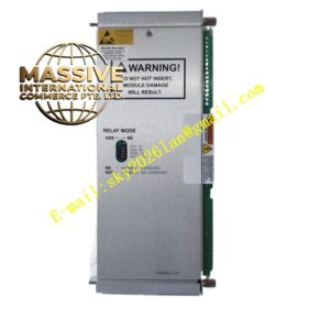
Bently 3500/33‑01‑00 (149992‑01)
- Key Features: Sixteen independent single‑pole double‑throw SPDT relay contacts; every relay supports freely configurable AND‑OR combined voting logic; relay group configurable for normally‑energized or normally‑de‑energized working mode; each relay contact fitted with built‑in arc‑suppression circuit; hot‑swap maintainability; front‑panel multi‑color LED status indicators; relay output status readable via rack configuration software; supports complex multi‑channel cross‑voting protection logic for SIL‑capable machinery‑protection systemsBaker Hugh….
- Technical Specifications & Performance Parameters
- Relay channel quantity: 16 SPDT relay outputs
- Typical power consumption: 5.8 W
- Operating temperature: 0 ℃ ~ +60 ℃
- Storage temperature: ‑40 ℃ ~ +85 ℃
- Resistive contact rating: 2 A @ 250 Vrms
- Weight: 0.70 kg
- Material Composition: FR‑4 multilayer printed‑circuit board; industrial‑grade logic‑processing chip; epoxy‑sealed SPDT electromagnetic relay components; built‑in arc‑suppression absorbing components; gold‑plated back‑plane edge connector; metal front‑panel with multi‑color LED indicators; reinforced plastic mechanical locking latch assembly.
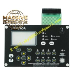
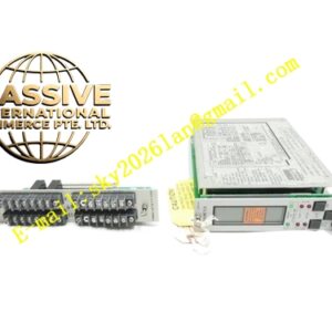
- Structural Features: Full‑height plug‑in rack‑module mechanical structure; front‑panel OK and TX/RX LED indicators for module health and bus communication; rear‑side gold‑plated edge connector mates with rack back‑plane bus; all relay field‑wiring connects to matched external I/O termination module; mechanical latch locks module firmly inside rack slot.
- Working Principle: Module continuously reads alert, danger, module‑not‑ok status bits from every monitor module over rack back‑plane bus. Internal logic processor executes user‑downloaded AND‑OR voting logic rules. When combined logic condition is satisfied, corresponding SPDT relay coil energizes or de‑energizes, changes contact state. Relay hard‑contact signals transmit to external DCS, safety interlock system and local alarm annunciators through external I/O termination wiringBaker Hugh….
- Application Scenarios: Hard‑contact alarm and trip signal output for steam‑turbine and centrifugal‑compressor machinery‑protection racks; multi‑channel cross‑voting safety‑interlock logic implementation; driving on‑site local alarm annunciator panels; petrochemical and thermal‑power‑plant TSI system hard‑wired safety‑signal output.
- Installation Requirements: Insert full‑height relay output module into available rack slot on right side of TDI module; fully engage mechanical locking latch; install matched external I/O termination module and complete field‑relay‑contact wiring; configure relay voting logic, relay energize mode via 3500 rack configuration software; execute relay self‑test function to verify contact switching performance.
- Usage Notes: Implement ESD anti‑static protection during module handling and replacement; strictly follow official maintenance procedure for hot‑swap operation; strictly respect relay contact rated current‑voltage limit, do not overload relay contacts; inspect front‑panel communication LED status during daily inspection rounds; save complete rack‑configuration backup file after modifying any relay‑logic parameters.