Description
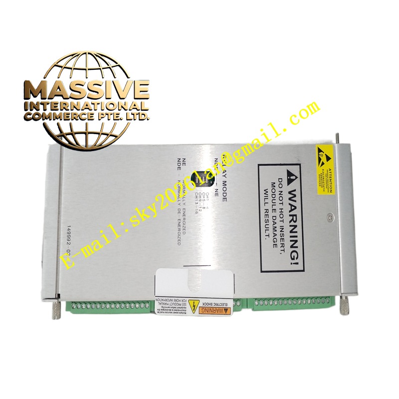
Bently 3500/44‑01‑00
Technical Specifications:
- Module Form: Full‑height 3500 rack‑slot module
- Input Channel Quantity: 4 configurable input channels
- Supported Input Types: Seismic velocity sensor input, dynamic pressure sensor input
- Specialized Algorithm: Dedicated filtering and calculation algorithm for aeroderivative gas turbine vibration feature
- Alarm Function: Independent Alert and Danger alarm threshold setting for each channel
- Relay Output: Configurable alarm relay contact outputs
- Recorder Output: Per‑channel 4‑20 mA analog recorder output
- Communication: Data transmission via 3500 rack back‑plane to gateway module
- Hot‑Swap Capability: Support powered hot‑swap replacement
- Operating Temperature: ‑30 °C ~ +65 °C
- Storage Temperature: ‑40 °C ~ +85 °C
- Humidity: 5‑95% RH non‑condensing
- Maximum Power Consumption: 13 W
- Built‑in Diagnosis: Hardware self‑diagnosis, sensor‑loop fault detection Functional Features:
- Specially designed hardware and algorithm matching aeroderivative gas‑turbine vibration characteristics, different from general‑purpose vibration monitor modules.
- Accept both seismic velocity sensor and dynamic pressure sensor input for gas‑turbine casing vibration and combustion dynamic‑pressure monitoring.
- Each channel supports independent Alert and Danger alarm threshold setting for machinery protection logic.
- Per‑channel 4‑20 mA recorder analog output transmits measurement value to external control system.
- Hot‑swap function supports module replacement without shutting down 3500 rack power supply.
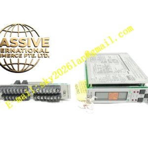
- Front‑panel LED indicators display module health status, channel alarm status for quick on‑site fault identification.
- All parameters configured via 3500 configuration software, no hardware jumper adjustment needed.
- Capture high‑frequency transient vibration signals occurring during aeroderivative gas‑turbine start‑up, load change and trip events. Application Scenarios: Vibration protection monitoring for aeroderivative gas turbines such as FT4, FT8 series; dynamic combustion pressure monitoring for gas‑turbine combustor section; gas‑generator and power‑turbine casing vibration measurement; combined‑cycle power plant gas‑turbine machinery protection system. Performance Parameters: High‑precision sampling for high‑frequency vibration signal; fast alarm response speed; excellent anti‑interference performance for gas‑turbine cabinet electromagnetic environment; high MTBF value for long‑term continuous operation. Material Composition: Mixed‑signal multi‑layer PCB board; industrial high‑speed signal‑processing chip; relay components; metal front‑panel; plastic module frame; gold‑plated rack back‑plane edge connector. Structural Characteristics: Full‑height module form‑factor for 3500 rack slot; metal front‑panel with status LED indicators; rear gold‑plated edge connector connects with rack back‑plane; front removable terminal block for sensor input and relay‑output wiring connection. Working Principle: Seismic sensor or dynamic‑pressure‑sensor analog signals are fed into module via front‑side terminal block. Internal circuit implements signal conditioning, filtering and high‑speed analog‑digital conversion. Dedicated aeroderivative‑gas‑turbine algorithm processes digital signal and computes vibration parameters. Measured values compare with preset Alert and Danger threshold to trigger alarm relay action. Measurement data transmits to communication gateway through rack back‑plane. Recorder circuit converts digital measurement value to 4‑20 mA analog signal. On‑board self‑diagnosis circuit continuously monitors module hardware and sensor‑loop health status. Installation Requirements:
- Insert module into full‑height slot of 3500 rack, push module fully seated, fasten front‑panel locking screws.
- Connect seismic sensor, dynamic‑pressure sensor and relay output wiring to front removable terminal block strictly following official wiring drawing.
- Complete channel‑type selection, measuring‑range setting and alarm‑threshold configuration using 3500 rack configuration software, download parameters into rack.
- Verify rack power supply is within normal operating range, check front‑panel LED indication after power‑on completion. Usage Notes:
- Hot‑swap action should only target module insertion‑removal. Do not touch rear gold‑plated edge connector while rack remains powered.
- All configuration parameters must be downloaded into rack before putting protection function online.
- Do not exceed rated contact load of alarm relay terminals. For high‑load application external intermediate relay shall be adopted.
- Check terminal‑block screw tightness during equipment overhaul to avoid signal fault caused by loose contact.
- Module housing shall not be opened. On‑site repair is not supported; replace complete module upon hardware failure.