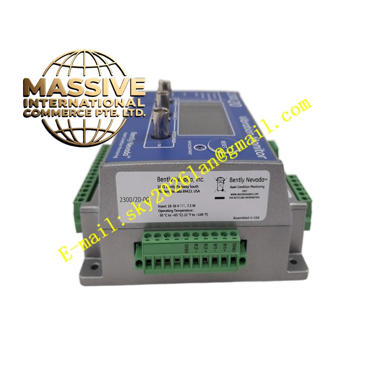
Description
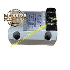
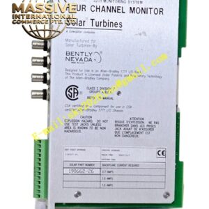
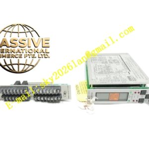
Bently 3500-50-01-00
Technical Specifications
- Module Type: Tachometer / Speed Monitor
- Input Types: Magnetic Pickup, Proximity Probe, Keyphasor
- Speed Range: Typically 0 to 30,000 RPM (dependent on sensor and gear ratio)
- Accuracy: ±1 RPM typical
Functional Features
- Overspeed Protection: Provides independent, programmable overspeed trip relays for critical machine safety.
- Multi-Event Support: Supports multiple pulses per revolution for high-resolution speed measurement.
- Zero-Speed Detection: Accurately detects machine stop condition for barring gear or turning gear monitoring.
- Startup/Shutdown Tracking: Captures speed data during machine coast-down and acceleration for critical speed avoidance.
Application Scenarios
Essential for all rotating machinery, particularly steam and gas turbines where overspeed protection is a critical safety requirement, and for monitoring compressor and pump operating speeds.
Performance Parameters
- Input Frequency Range: Wide bandwidth to accommodate various gear ratios and tooth counts
- Response Time: Fast speed update rate for real-time protection
- Signal Conditioning: Automatic gain control for consistent operation across varying signal amplitudes
Material Composition
Built with high-reliability components and robust signal conditioning circuitry designed for continuous industrial duty.
Structural Characteristics
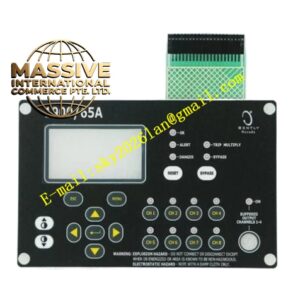
Standard 3500 module form factor with front-panel speed display, status LEDs, and configuration switches, plus rear I/O connectors for sensor inputs and backplane communication.
Working Principle
Counts the number of pulses from the speed sensor over a precise time base, calculates rotational speed, and continuously compares the measured value against programmed overspeed and underspeed alarm setpoints.
Installation Requirements
Install in any available monitor slot. Configure the number of teeth/gear ratio and sensor type to match the field installation. Verify speed reading accuracy against a calibrated reference.
Usage Precautions
Ensure the speed sensor is properly installed with correct air gap. Never rely solely on software overspeed protection; always verify independent hardware trip circuits for critical applications.