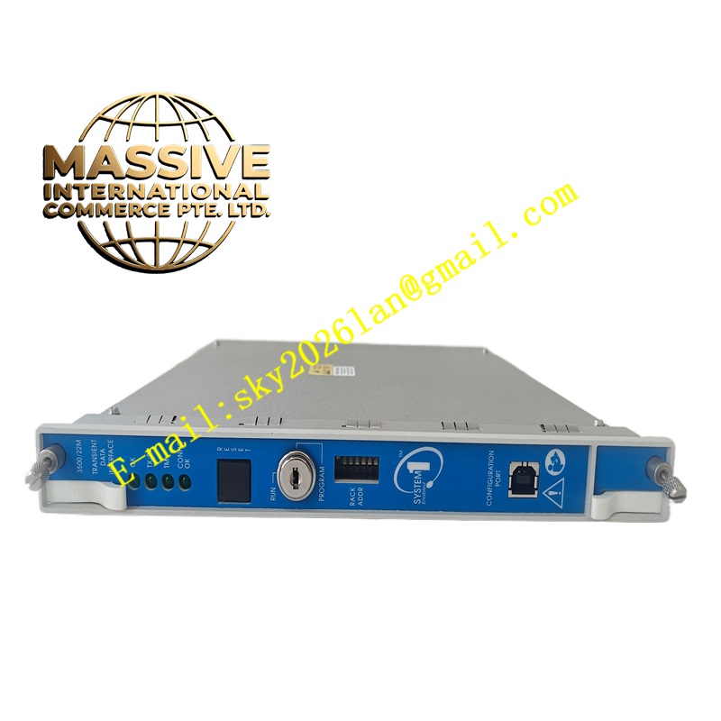
Description
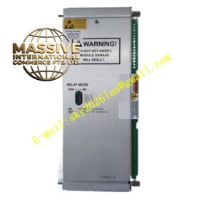
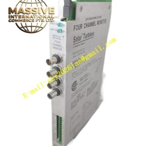
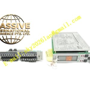
Bently 3500/62‑01‑00 | Part Number:136499‑01
Technical Specifications:
- Input Channel Quantity: 8 analog process variable input channels
- Supported Input Signal: ±10 VDC voltage, 4‑20 mA current
- Signal Circuit Isolation: 500 Vdc isolation between field side and system side
- Power Consumption:7 Watts nominal
- Operating Temperature:0°C ~ +60°C
- Storage Temperature:‑40°C ~ +85°C
- Rack Slot Occupation:1 slot
- Certifications: SIL2, CE, UL certification Functional Features:
- Accepts standard industrial 4‑20mA and ±10VDC transmitter signals
- 500V galvanic isolation between field signal and system internal circuit
- Each channel supports independent high‑alarm and danger‑alarm programmable setpoints
- Supports signal scaling function to convert raw electrical signal into physical engineering unit
- Built‑in input signal fault detection for over‑range and under‑range status
- Channel bypass function for maintenance without interrupting other channels
- Alarm events can drive 3500 series relay modules for protection interlock Application Scenarios:
- Centrifugal compressor suction / discharge pressure monitoring
- Turbine lubricating oil pressure and oil temperature auxiliary signal monitoring
- Industrial fan, pump unit process parameter monitoring integrated with machinery protection
- Power plant, oil‑gas, chemical industry sites need to incorporate process transmitter signals into 3500 protection system Performance Parameters:
- Input Measurement Accuracy: ±0.2% full scale
- Isolation Voltage:500 Vdc
- Signal Response Time: Less than 200ms
- 4‑20mA Input Burden Resistance: 125Ω
- ±10V Input Impedance: Greater than 100kΩ Material Composition:
- Front panel: Oxidized aluminum alloy
- Main circuit board: FR‑4 fire‑retardant printed circuit board with isolation components
- Shield housing: Cold‑rolled steel anti‑EMI shell
- Backplane bus connector: Gold‑plated industrial connector Structural Characteristics:
- Single‑slot plug‑in module for 3500 rack
- Front panel LED indicators: OK, Global Fault, Alarm, Bypass
- External termination design, field wiring connects to external termination block assembly 136499‑01 outside rack
- Mechanical locking screws on both sides for rack fastening Working Principle: Field 4‑20mA or ±10VDC signals are delivered to external termination block 136499‑01, then transmitted into module. Internal isolation circuit isolates field side interference. After signal conditioning and analog‑digital conversion, raw signal value is scaled into physical engineering value. Microcontroller compares measured value with user‑configured alarm thresholds. Alarm condition sends message to rack backplane bus to trigger relay action, and transmits measurement data to host monitoring software via communication gateway. Installation Requirements:
- Install module into single slot of 3500 instrument rack, power off rack before insertion or removal, non‑hot‑swap device
- Field transmitter wiring connects to external termination assembly 136499‑01, adopt shielded twisted‑pair cable
- Signal cable shield layer single‑end grounding at cabinet side
- Separate process signal wiring from high‑voltage power cable to avoid electromagnetic coupling interference
- Keep proper ventilation gap around module for heat dissipation Usage Notes:
- Configure signal type, scaling range and alarm threshold via 3500 configuration software before commissioning
- Do not apply voltage exceeding rated input range to input terminals
- Regularly inspect external termination block screw tightness
- Prevent dust and moisture from invading termination block
- Execute signal loop calibration at least once per year