Description
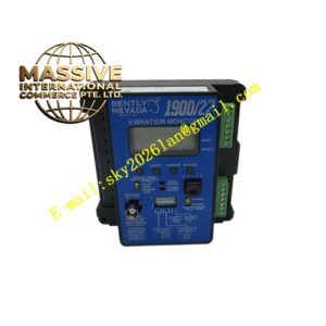
Bently Nevada 3300/10‑02‑02‑00
- Technical & Performance Parameters:
- Channel quantity: 2 measuring channels
- Input transducer: 3300 series eddy‑current proximity probe
- Measuring range: Configurable by jumper setting
- Frequency response: DC ~ several hundred Hz
- Analog output: Standard recorder signal
- Operating temperature: ‑40 °C ~ +70 °C
- Power supply: Supplied by 3300 rack backplane
- Material Composition: Metal front panel with channel status and alarm LED indicators; multilayer high‑stability PCB containing gap‑voltage signal conditioning circuit, threshold comparison circuit and alarm drive circuit; metal locking latch for rack installation.
- Structural Characteristics: Single‑width plug‑in module for 3300 rack chassis. Front panel has multi‑LED status indication. Rear edge connector connects rack backplane, two‑channel probe input, alarm bus and analog output. Supports hot‑swap inside rack.
- Working Principle: Receives gap‑voltage signal from eddy‑current proximity probes installed at thrust collar. Converts gap voltage value into rotor axial displacement value. Compares real‑time axial‑position value with pre‑programmed alert and danger thresholds. Triggers alarm relay output once threshold exceeded. Outputs axial‑position value via analog channel for external system recording.
- Application Scenarios: Axial thrust position monitoring and protection for steam turbines, gas turbines, large centrifugal compressors. Prevents thrust‑bearing failure caused by excessive rotor axial movement. Widely used in power‑generation and petrochemical critical rotating machinery.
- Installation Requirements: Install inside 3300 standard rack. Complete wiring for two thrust‑probe systems. Configure measuring‑range jumpers according to actual thrust travel. Adjust probe gap voltage to working point during commissioning. Separate probe signal cables from high‑interference cables. Guarantee rack heat‑dissipation condition.
- Usage Notes: Adjust probe gap carefully during commissioning. Verify mechanical thrust‑collar zero‑point calibration. Latched alarms need manual reset after fault removal. Never exceed module environmental operating limits. Check probe cable integrity regularly.