Description
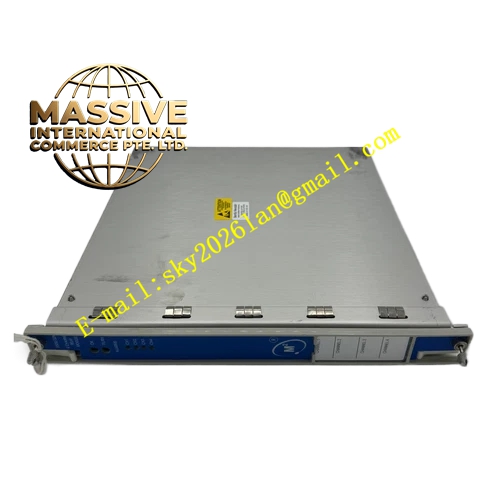
Bently Nevada 3300/20-11-01-02-00-02
Technical Specifications
- Full-Scale Range: 0.5-0-0.5 mm
- Transducer Input: 3300 or 7200 Proximitor systems, 200 mV/mil
- Input Impedance: 10 kΩ
- Sensitivity: 200 mV/mil (8 V/mm)
- Signal Conditioning Accuracy: ±0.33% typical, ±1% maximum at +25°C
- Alarm Relay Option: Hermetically sealed
- Safety Barrier: Internal barrier
- Recorder Outputs: +4 to +20 mA, 0 to -10 Vdc, or +1 to +5 Vdc
- Power Consumption: 1.5 watts nominal
- Operating Temperature: -20°C to +65°C
- Storage Temperature: -40°C to +85°C
- Humidity: 95% non-condensing
Functional Features
- Dual independent channels for thrust position redundancy
- Direct gap measurement and thrust position calculation
- Programmable alarm setpoints for Alert and Danger conditions
- Internal safety barriers eliminating external barrier requirements
- Hermetically sealed relays for high-reliability switching
- Recorder outputs for trending and control system integration
- Front panel meter display of measured values
Application Scenarios
- Thrust bearing wear monitoring on large turbines
- Axial position measurement on compressors and pumps
- Motor rotor thrust monitoring
- Generator thrust pad condition assessment
- Machinery protection systems requiring internal barriers
Performance Parameters
- High repeatability with 1 µm resolution
- Fast response to axial position changes
- Stable output signals with low drift
- Accurate gap voltage interpretation over temperature range
- Reliable relay operation under continuous duty
Material Composition
- Chassis: Painted steel or aluminum
- Front panel: Clear anodized aluminum with silkscreened legends
- Internal circuits: Epoxy-fiberglass printed wiring boards
- Relays: Hermetically sealed reed or armature types
- Barrier components: Precision resistors and zener diodes
Structural Characteristics
- Standard 3300 monitor module footprint
- Front panel meter for local indication
- Rear terminal strip or connector for field wiring
- Plug-in jumper configuration for range and output selection
- Rack-mounted in 3300 system chassis
Working Principle Two proximity probes mounted facing the thrust collar generate DC gap voltages proportional to the axial clearance. The monitor converts these voltages into position readings referenced to the machine’s thrust bearing clearance. As the rotor shifts axially due to thrust loading or bearing wear, the monitor tracks this movement. If the position exceeds the Alert or Danger threshold in either the active or inactive thrust direction, the corresponding relay changes state to annunciate the alarm.
Installation Requirements
- Probes must be mounted to observe the thrust collar directly
- Initial gap must be set within the linear range of the transducer system
- Internal barriers require proper grounding to the rack earth
- Recorder output load must not exceed the drive capability
- Verify barrier compatibility with the hazardous area classification
Usage Precautions
- Thrust position alarms must be set with adequate margin from mechanical limits
- Regular verification of probe gap voltage prevents measurement drift
- Do not exceed the internal barrier voltage or current ratings
- Hermetic relays should be tested periodically for contact integrity
- Ensure both channels are powered before enabling Danger trip logic