Description
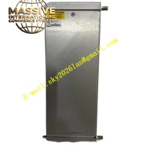
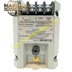
Bently Nevada 3300/20-12-01-00-00-00
Technical Specifications
| Parameter | Specification |
|---|---|
| Channels | Two independent thrust position channels |
| Input | 3300 or 7200 series proximity probes (200 mV/mil) |
| Full-Scale Range | ±25 mils (configuration 12) |
| Input Impedance | 10 kΩ |
| Input Voltage | 24 VDC |
| Output Signal | 4–20 mA and system interface signals |
| Alarm Relays | Epoxy-sealed (configuration 01) |
| Operating Temperature | -40°C to +85°C |
| Communication | Modbus RTU |
| Weight | 1.0 kg |
| Mounting | Rack-mountable module |
| Origin | USA |
Functional Features
- Continuously monitors thrust bearing wear and axial shaft position
- Provides early warning of thrust bearing degradation
- Prevents catastrophic equipment failure from axial rotor contact
- Features two independent channels for redundant monitoring
- Offers four alarm setpoints (two over and two under per channel)
- Includes front-panel LCD display showing magnitude and direction
- Provides recorder outputs for trending and analysis
- Supports Danger Bypass function for maintenance activities
- Includes NOT OK checking for transducer and wiring integrity
Structural Characteristics The monitor module is constructed with a rugged metal housing designed for rack mounting in 3300 series chassis. The front panel features a vertical bargraph LCD with 63 segments per channel, green OK LEDs, red Alert and Danger LEDs, and a red Bypass LED. The rear panel includes terminal blocks for field wiring, coaxial connectors for buffered transducer outputs, and relay output contacts. The internal circuit boards are conformal coated to resist moisture, dust, and chemical contamination.
Working Principle Two proximity probes mounted on either side of the thrust bearing collar generate voltage signals proportional to the axial gap between probe tip and shaft surface. The monitor processes these signals to determine the axial position of the rotor relative to the thrust bearing. As the thrust bearing wears or thermal expansion occurs, the shaft moves axially. The monitor detects this movement, compares it against programmed alarm thresholds, and activates relays when dangerous axial displacement is detected. The dual-channel configuration allows comparison between two measurement points for enhanced diagnostic capability.
Installation Requirements
- Install proximity probes facing thrust collar surfaces at recommended gap distances
- Mount probes at 90-degree offset positions when possible for best coverage
- Use shielded coaxial cable for all transducer connections
- Maintain cable shield continuity to single-point ground
- Verify probe orientation matches upscale direction configuration
- Program alarm setpoints based on manufacturer thrust bearing clearance limits
- Test Danger Bypass function during commissioning
Application Scenarios
- Steam turbine thrust bearing monitoring
- Gas compressor axial position protection
- Large pump thrust bearing supervision
- Generator thrust pad condition monitoring
- Refinery centrifugal compressor protection
- Marine propulsion thrust bearing monitoring