Description
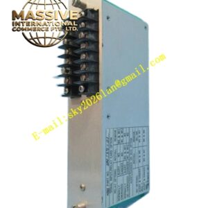
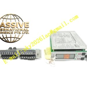
Bently Nevada 3300/36
Technical Specifications
| Parameter | Specification |
|---|---|
| Measurement Type | Rotational speed (RPM) |
| Input | Proximity probe or magnetic pickup |
| Setpoints | Dual independent alarm setpoints |
| Relay Options | Available with or without alarm relays |
| Operating Temperature | 0°C to +65°C |
| Storage Temperature | -40°C to +85°C |
| Humidity | 95% noncondensing |
| Dimensions | Standard 3300 rack module format |
| Weight | Approximately 0.8 kg |
| Origin | USA |
Functional Features
- Provides high-precision rotational speed measurement
- Features dual independent setpoints for overspeed and underspeed alarms
- Uses non-contacting measurement for zero mechanical wear
- Offers high resolution for detection of small speed changes
- Provides multiple probe configurations for different applications
- Features high interchangeability between probes, cables, and sensors
- Includes front-panel display for direct speed reading
- Supports latching and non-latching alarm modes
- Performs continuous transducer OK verification
Structural Characteristics The tachometer module is housed in a standard 3300 series metal enclosure with a front panel containing an LCD display, LED status indicators, and adjustment switches. The unit accepts input from a single proximity probe or magnetic pickup mounted to observe a keyway, gear tooth, or reflective tape on the rotating shaft. The internal circuitry includes signal conditioning amplifiers, zero-crossing detectors, frequency-to-voltage converters, and microprocessor-based measurement engines.
Working Principle A proximity probe or magnetic pickup mounted near the rotating shaft detects the passage of keyways, gear teeth, or other discontinuities. Each passage generates an electrical pulse. The tachometer measures the time between successive pulses and calculates the rotational speed in RPM. The microprocessor compares the measured speed against two independent alarm setpoints. When an overspeed or underspeed condition is detected, the monitor activates alarm relays and updates the front-panel display. The unit continuously verifies transducer signal integrity to ensure measurement reliability.
Installation Requirements
- Mount the probe or pickup to observe a keyway or gear tooth on the shaft
- Maintain proper gap distance between probe tip and shaft surface
- Use shielded cable for transducer connections
- Route signal cables away from high-energy power cables
- Program setpoints based on machinery operating speed limits
- Verify pulse signal quality at the monitor input terminals
- Test alarm relay operation at both overspeed and underspeed conditions
Application Scenarios
- Steam turbine overspeed protection
- Gas turbine speed monitoring
- Generator rotational speed supervision
- Compressor speed control systems
- Pump overspeed protection
- Industrial fan and blower speed monitoring
- Marine propulsion shaft speed measurement