Description
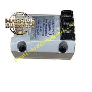
Bently Nevada 3300/45
Technical Specifications
| Parameter | Specification |
|---|---|
| Channels | Two independent differential expansion channels |
| Input | Proximity probe transducer signals |
| Full-Scale Range Options | 0–5 mm, 0–10 mm, 0.25–0–0.25 in, 0–0.5 in, 10–0–10 mm, 0–20 mm, 0.5–0–0.5 in, 0–1.0 in |
| Transducer Input Options | 25 mm, 35 mm, or 50 mm proximity probes |
| Input Impedance | 10 kΩ |
| Alarm Setpoints | Four per channel (two over, two under) |
| Input Voltage | 24 VDC |
| Output Signal | 4–20 mA recorder output |
| Operating Temperature | 0°C to +65°C |
| Dimensions | 16 cm × 16 cm × 12 cm |
| Weight | 0.8 kg |
| Origin | USA |
Functional Features
- Provides two channels of continuous differential expansion monitoring
- Monitors both magnitude and direction of thermal expansion
- Offers four alarm setpoints per channel (two over, two under)
- Allows Channel B to be turned OFF for single-location measurements
- Includes front-panel LCD display with magnitude and direction indication
- Features LED indicators for OK, Alert, Danger, and Bypass status
- Provides recorder outputs for trending and data acquisition
- Supports programmable alarm delays and relay logic
- Performs continuous transducer OK verification
Structural Characteristics The monitor is housed in a standard 3300 series module enclosure with a front panel containing an 83 mm vertical bargraph LCD, green OK LEDs, red Alert and Danger LEDs, and red Bypass LEDs. The rear panel provides terminal blocks for field wiring, coaxial connectors for buffered transducer outputs, and relay contact terminals. The internal circuitry includes signal conditioning, linearization, and microprocessor-based measurement and alarm logic.
Working Principle A proximity probe mounted on the machine casing observes an axial surface or collar on the rotor. As the machine heats during startup, the rotor and casing expand at different rates, causing relative axial movement. The proximity probe detects this movement as a change in gap distance. The monitor converts the probe voltage signal into a linear displacement reading, compensates for transducer nonlinearities, and displays the differential expansion value. When the expansion exceeds safe limits, the monitor activates alarm relays to alert operators or trigger automatic shutdown sequences.
Installation Requirements
- Mount proximity probe to observe an axial collar or surface on the rotor
- Ensure probe mounting is rigid and thermally stable
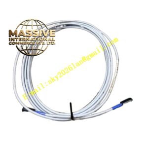
- Use shielded coaxial cable for transducer connections
- Maintain cable shield continuity to single-point ground
- Program full-scale range to match expected differential expansion
- Set alarm thresholds based on manufacturer axial clearance limits
- Verify measurement accuracy during known thermal transients
Application Scenarios
- Steam turbine differential expansion monitoring
- Generator rotor-to-stator thermal growth measurement
- Large compressor casing expansion supervision
- Refinery turbine supervisory instrumentation
- Power plant startup thermal monitoring
- Industrial gas turbine expansion protection