Description
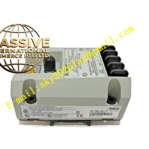
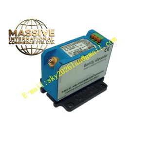
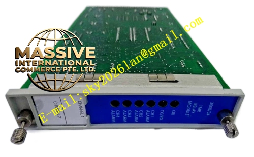
Bently Nevada 3300/46
Technical Specifications
| Parameter | Specification |
|---|---|
| Input | Two proximity probe transducer signals |
| Input Impedance | 10 kΩ |
| Signal Scale Factor | 100 mV/mil (4 V/mm), 20 mV/mil (0.787 V/mm), or 10 mV/mil (3.92 V/mm), jumper-selectable |
| Ramp Angle | Programmable from 4 to 45 degrees in 1-degree increments |
| Accuracy | Within ±0.33% of full-scale typical, ±1% maximum |
| Power Consumption | 1.5 watts nominal |
| Recorder Output | 4–20 mA, 0 to -10 Vdc, or 1–5 Vdc |
| Alarm Setpoints | Four per channel (two over, two under) |
| Operating Temperature | 0°C to +65°C |
| Storage Temperature | -40°C to +85°C |
| Weight | 1.4 kg |
| Dimensions | 5.1 cm × 20.3 cm × 33.0 cm |
| Origin | USA |
Functional Features
- Uses ramp surface measurement technique for extended range
- Provides increased monitoring range with smaller transducers
- Offers flexible transducer mounting locations
- Displays both magnitude and direction of differential expansion
- Features four programmable alarm setpoints per channel
- Supports dual or single ramp configuration options
- Includes programmable ramp angle from 4 to 45 degrees
- Provides recorder outputs for trending and analysis
- Features front-panel LCD display and LED status indicators
- Performs continuous self-diagnostics and transducer OK checking
Structural Characteristics The monitor module is constructed with a main circuit board, optional expander board, and front panel assembly housed in a rugged metal enclosure. The front panel features a vertical bargraph LCD with 63 segments, green OK LEDs, red Alert and Danger LEDs, and red Bypass LEDs. The rear panel includes terminal blocks for field wiring, coaxial connectors for buffered transducer outputs, and relay output contacts. The unit is designed for rack mounting in standard 3300 series chassis.
Working Principle Two proximity probes observe ramp surfaces machined onto the rotor at a known angle (typically 4–45 degrees). As the rotor expands axially relative to the casing, it also moves radially along the ramp surface. The proximity probes detect the radial movement, which is geometrically related to the axial expansion by the tangent of the ramp angle. The monitor calculates the axial differential expansion from the measured radial displacement and the programmed ramp angle. This technique effectively multiplies the transducer linear range by the geometric ratio, allowing measurement of very large thermal growth with standard probes.
Installation Requirements
- Machine ramp surfaces onto rotor with precise angle control
- Mount two proximity probes to observe ramp surfaces
- Program ramp angle to match machined surface angle
- Use shielded coaxial cable for all transducer connections
- Maintain probe-to-ramp surface gap within linear range
- Verify geometric calculation during commissioning
- Set alarm thresholds based on calculated axial expansion limits
Application Scenarios
- Large steam turbines with excessive thermal growth
- Generators where standard probe ranges are insufficient
- Compressors with limited collar mounting space
- Machines requiring differential expansion monitoring without convenient collar locations
- Refinery large rotating equipment protection
- Power plant turbine supervisory instrumentation