Description
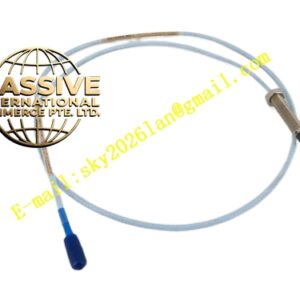
Bently Nevada 330106‑05‑30‑50‑02‑00
Technical Specifications: Probe tip diameter: 8 mm Built‑in armored‑cable length: 5.0 m Mechanical structure: reverse‑mount configuration Outer cable protection: stainless‑steel flexible metal armor Scale factor: 7.87 V/mm Linear measuring range: 0.25 mm‑2.3 mm Recommended working gap: 1.27 mm Frequency response: DC‑10 kHz Cable rating: standard‑temperature armored‑cable configuration
Functional Features: Reverse‑mount installation mechanical‑structure Built‑in metal‑armored cable resists extrusion, pulling‑force and sharp‑object cutting damage Full interchangeability with 3300 XL 8 mm‑series proximitor sensors and extension‑cable assemblies Non‑contact measuring mode Low temperature‑drift performance Superior mechanical‑damage‑resistant performance for harsh heavy‑industrial field‑environment
Application Scenarios: Vibration and displacement monitoring for rotating‑machinery equipment deployed at sites with severe cable‑mechanical‑abrasion risk. Typical deployment includes heavy‑industry plants, steel‑mill facilities and open‑air equipment zones. Works together with reverse‑mount probe‑housing assembly for external probe‑gap adjustment.
Performance Parameters: Probe tip operating temperature: −52 °C ~ +177 °C Armored‑cable operating temperature: −52 °C ~ +177 °C Probe coil resistance: 8.73 Ω ±0.5 Ω for 5‑meter‑cable version Maximum relative humidity: 93 % non‑condensing Scale‑factor tolerance: ±5 % across full linear measuring range
Material Composition: Probe tip: high‑temperature epoxy encapsulation Reverse‑mount probe housing: 316 stainless steel Internal sensing coil: high‑temperature enameled copper wire Inner‑cable insulation: fluoropolymer insulating material Outer‑layer protection: stainless‑steel flexible metal‑armor sheath Connector assembly: nickel‑plated alloy circular connector
Structural Features: Reverse‑mount probe‑body geometry matching probe‑housing assembly 5‑meter built‑in armored‑cable assembly Stainless‑steel flexible outer‑armor protective layer Hermetically sealed probe‑tip assembly Tri‑axial shielded inner signal conductors Locking‑type miniature circular connector Built‑in strain‑relief structure at probe‑cable joint to prevent core‑wire breakage caused by pulling‑force load
Working Principle: Eddy‑current effect governs measurement function. Probe internal coil generates high‑frequency alternating magnetic field and induces eddy currents on measured metal‑target surface. Gap‑distance variation changes probe‑coil impedance. Proximitor sensor converts impedance variation into analog DC‑voltage signal proportional to clearance between probe tip and target surface. Metal‑armor layer only provides mechanical‑protection function and does not interfere with internal signal‑transmission behavior.
Installation Requirements: Cooperate with matched reverse‑mount probe‑housing assembly Maintain probe‑tip perpendicular orientation to target metal surface after installation Do not apply heavy pulling‑force load directly upon probe‑cable joint position Reserve proper cable slack for equipment thermal‑expansion and mechanical‑vibration displacement Follow armored‑cable‑specification minimum‑bending‑radius requirement Signal‑cable routing maintains physical separation from high‑voltage power‑cable routes Fully lock connector after wiring completion
Usage Notes: Do not cut, disassemble or modify metal‑armor layer and inner signal‑cable assembly Avoid sharp‑object scratching and heavy‑extrusion damage acting upon armored‑cable outer surface Prevent mechanical‑impact damage to probe tip during installation and gap‑adjustment procedure Confirm probe tip will not collide with rotating‑shaft surface under maximum equipment thermal‑expansion displacement Measured target surface must maintain exposed bare‑metal condition Periodically inspect armored‑cable outer‑surface integrity and connector anti‑loose state during long‑term equipment running