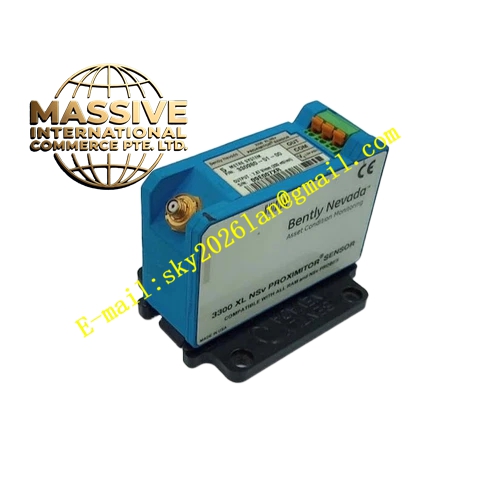
Description
Bently Nevada 330425-01-05
Technical Specifications:
- Sensitivity: 2.5 mV/m/s² (25 mV/g) ±5%
- Acceleration Range: 735 m/s² (75g) peak
- Frequency Response: 10 Hz to 15 kHz (±3 dB)
- Linearity: ±1% to 75g peak
- Input Voltage: -24 ± 0.5 Vdc
- Operating Temperature: -55°C to +121°C
- Mounting Thread: ¼-28 UNF (imperial, indicated by -01 suffix)
- Agency Approvals: CSA, ATEX, IECEx (indicated by -05 suffix)
- Connector: 3-pin
- Housing Material: 316L stainless steel
Functional Features:
- All functional features are identical to the 330425-02-05
- The ¼-28 UNF imperial thread mounting stud accommodates machines with imperial-threaded mounting provisions
- Extended acceleration range for high-vibration applications
- Multiple international hazardous area certifications
Application Scenarios:
- Same applications as the 330425-02-05
- Specifically selected for machines with ¼-28 UNF threaded mounting holes
- Common in North American installations where imperial fasteners are standard
- High-vibration gearboxes, compressors, and turbines in hazardous areas
Performance Parameters:
- Sensitivity: 25 mV/g ±5%
- Dynamic Range: 75g peak
- Frequency Range: 10 Hz to 15 kHz
Material Composition: Piezoelectric ceramic crystal in 316L stainless steel housing
Structural Features: Cylindrical body with ¼-28 UNF mounting stud. 3-pin top connector. Hermetically sealed.
Working Principle: Identical to the 330425-02-05. Piezoelectric charge generation proportional to acceleration, converted to voltage output by internal IC electronics.
Installation Requirements:
- Mount using the ¼-28 UNF threaded stud into the machine mounting hole
- Apply proper torque to ensure rigid mechanical coupling
- Connect 3-conductor shielded cable to the 3-pin connector
- Route cables away from EMI sources