



Description
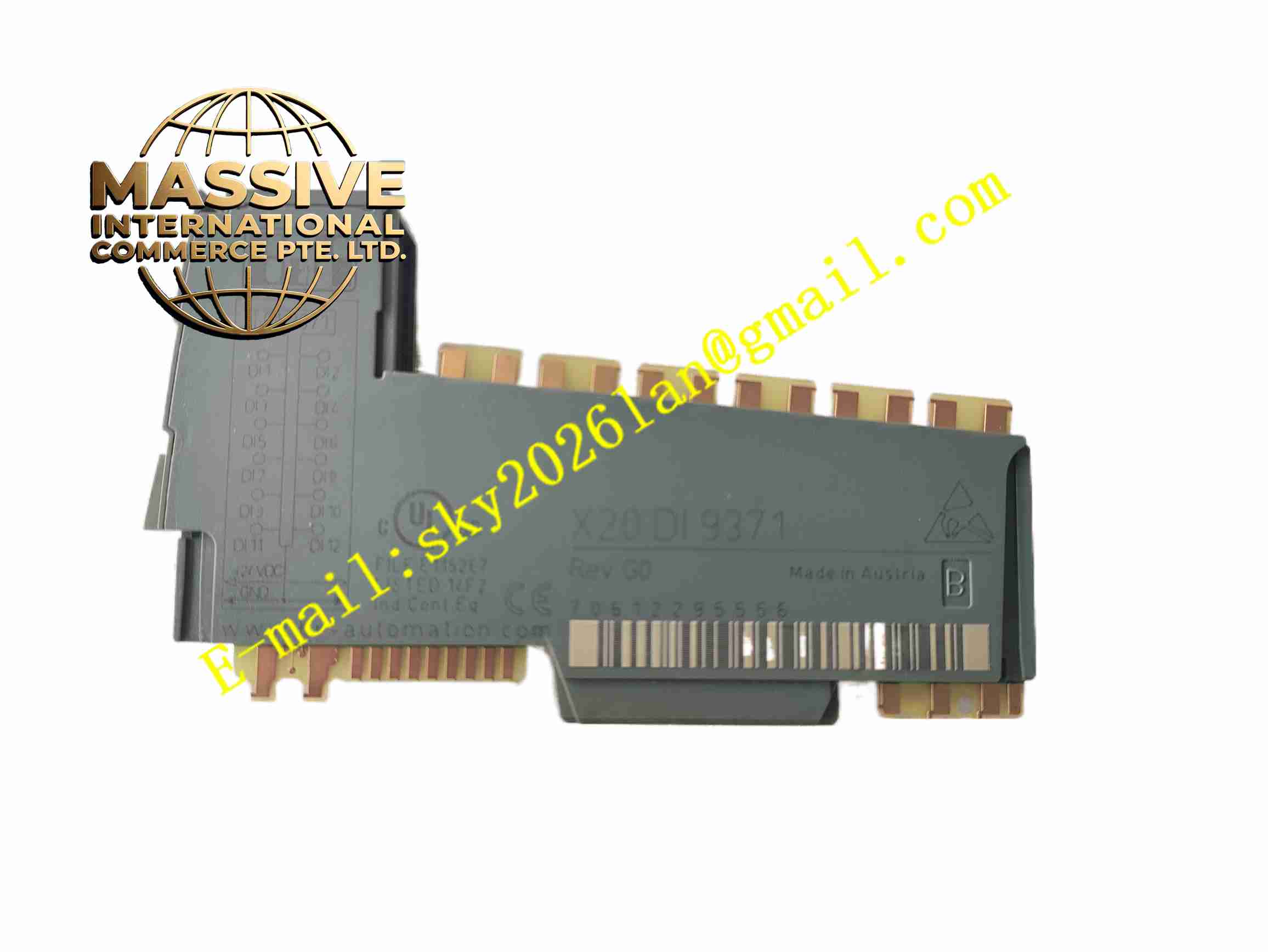
B&R X20DI9371
Technical Specifications: Channel count: 12 digital input channels Input type: Sink input, 1-wire connection Rated input voltage: 24VDC Input filter: Configurable digital filter Bus interface: X2X Link internal bus Power consumption: 1.75W for I/O circuit, 0.18W for bus circuit Operating temperature: 0℃ to 55℃ Humidity: Up to 100% non-condensing Protection class: IP20 Certifications: CE, UKCA, ATEX Zone2, UL, DNV, CCS
Functional Features: 12 independent 24VDC digital sink input channels. Configurable input filter to eliminate contact bounce and noise interference. Module run and fault diagnosis with LED indication and software alarm. X2X Link high speed backplane bus communication. Hazardous location certification for Zone 2 and Class I Div 2. Support hot swap for module replacement during system operation. Channel status data transmitted to X20 controller in real time.
Application Scenarios: Machine tool signal collection, packaging machinery digital signal acquisition, material handling conveyor system, textile machinery, marine automation control, food processing machine I/O system, petrochemical auxiliary equipment in Zone2 hazardous area.
Performance Parameters: Fast signal transmission through X2X high speed backplane bus. Vibration resistance up to 4g. Continuous 24-hour operation capability.
Material Composition: FR4 industrial printed circuit board. Input signal optocoupler isolation chips. Flame retardant plastic module housing. Gold plated X2X Link backplane connector. 12-pin screw terminal block X20TB12.
Structural Features: Compact segmented X20 bus module structure. Front panel with LED indicators for module run, error and channel status. Side backplane connector for X2X Link bus connection. Screw terminal block for field sensor wiring. Modular stacking installation on X20 bus base module.
Working Principle: 24VDC field digital signals from sensors enter module through screw terminals. Optocoupler provides galvanic isolation between field side and internal bus circuit. Digital filter circuit removes contact bounce and electrical noise. Valid channel status data is sent via X2X Link bus to X20 controller. Module self-diagnosis circuit monitors module hardware state and triggers fault indication once anomaly detected.
Installation Requirements: Mount module on X20 bus base module in sequence. Use matched X20TB12 12-pin terminal block. Field wiring adopts twisted cables for digital input signals. Separate signal wiring and high power wiring. Install inside IP20 protected control cabinet.
Usage Notes: Do not apply voltage higher than 24VDC to input channels. Check terminal tightening torque after wiring. Verify input filter parameter setting to match field sensor characteristics. Cut off power before replacing terminal block or module. Inspect module status LED after power on.





