Description
Burkert SE35 00423924
Technical Specifications: Measured fluid: liquids and gases Nominal size: DN 15 to DN 50 Flow range: specified per nominal size Output signal: 4-20 mA, pulse or frequency Power supply: 24 VDC Process pressure: up to 10 bar Ambient temperature: -10 ℃ to 60 ℃ Protection class: IP65 Process connection: threaded or flanged
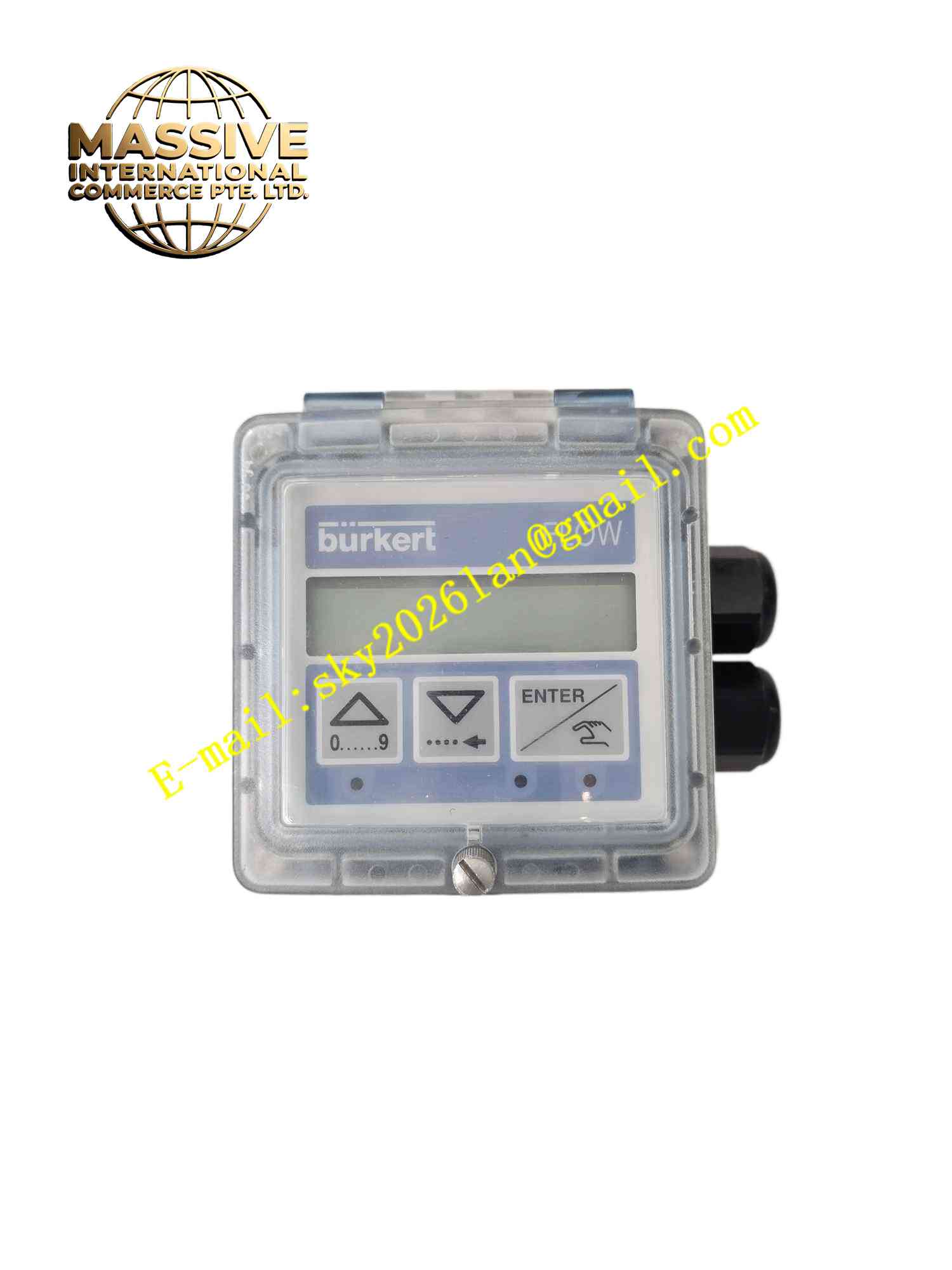
Functional Features: Inline flow measurement with no moving parts. Integrated flow conditioning improves accuracy. Standard 4-20 mA output proportional to flow rate. Pulse output for total flow counting. LED status indicators. Temperature compensation integrated. Easy setup via onboard push buttons.
Application Scenarios: Water treatment plant flow monitoring, chemical dosing system flow control, HVAC water balancing, coolant flow monitoring in machinery, beverage production fluid line measurement.
Performance Parameters: Measurement accuracy: ±1.5% of reading Repeatability: ±0.2% of reading Response time: 100 ms Pressure loss: specified per nominal size
Material Composition: Process housing: brass or stainless steel. Seals: EPDM or FKM elastomer. Electronics housing: PPS engineering plastic. Display window: polycarbonate. Cable gland: nickel-plated brass.
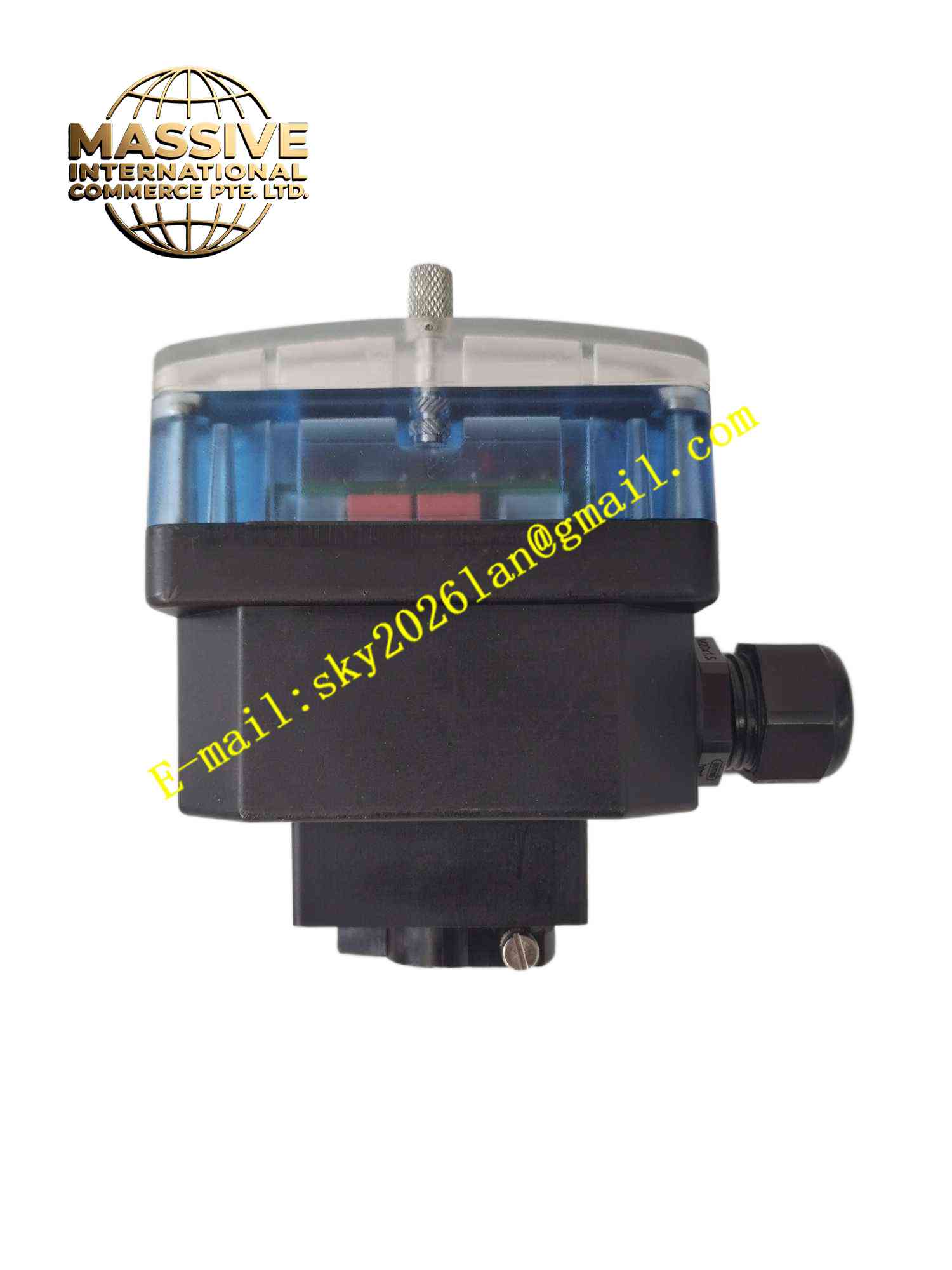
Structural Features: Inline cylindrical process housing. Electronic display unit mounted on top. Process thread connections at both ends. Cable gland for electrical connection. Sensor element integrated into flow path.
Working Principle: Fluid flows through inline sensor section. Sensor element detects flow velocity using calorimetric or turbine principle. Electronic circuit converts flow velocity measurement into standardized output signal. Microprocessor applies temperature compensation and flow calibration curve. Output signal updates proportionally to actual flow rate.
Installation Requirements: Install with adequate straight pipe run upstream and downstream. Ensure flow arrow matches actual flow direction. Keep device full of fluid during operation. Connect 24 VDC supply with correct polarity. Ground process piping for shield continuity.
Precautions for Use: Do not install in pipes subject to vibration. Use filter upstream to prevent particle damage. Do not exceed maximum process temperature. Periodically calibrate zero point. Protect display unit from mechanical impact. Do not apply pressure beyond rated maximum.