Description
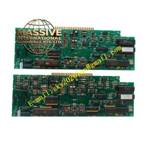
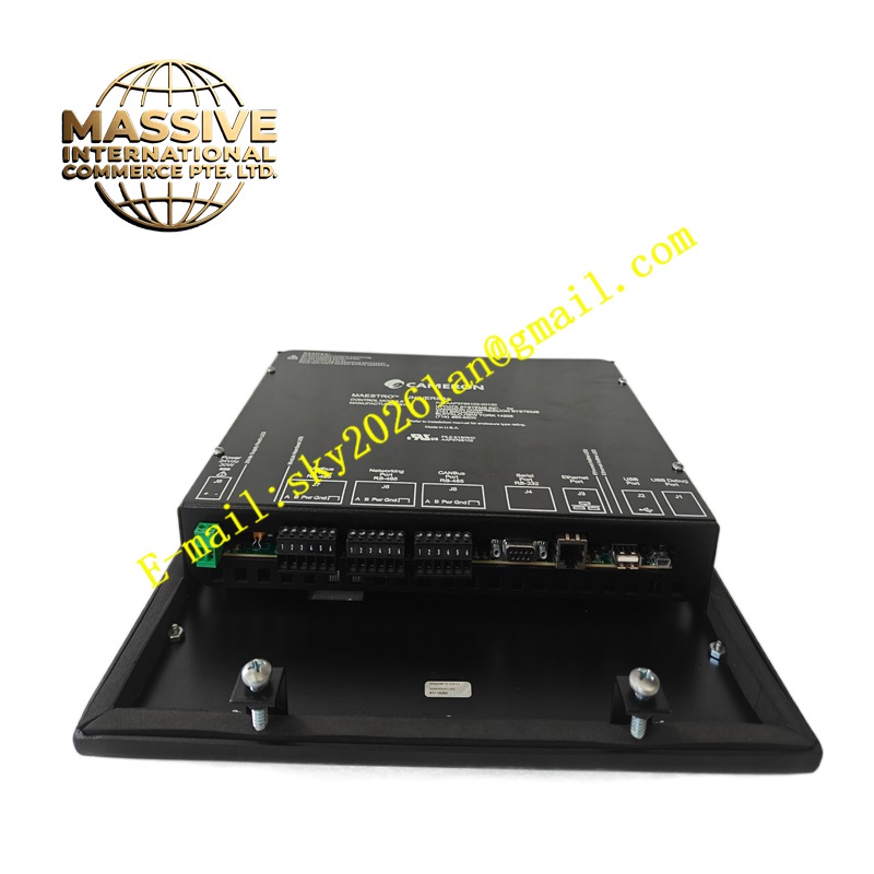
Cameron AAP3798102-00130
Technical Specifications 24V DC power supply; dual independent solenoid drive outputs; limit switch discrete input channels; Modbus RTU and HART communication interfaces; operating temperature -40°C to +70°C; IP67 ingress protection; NACE MR0175 corrosion resistant material specification; API 6A compliance for wellhead service.
Functional Features Drives two redundant solenoid coils for safety shutdown valve pilot circuits. Detects open coil, shorted coil and wiring faults on each solenoid channel. Reads valve open and closed limit switch signals to confirm mechanical valve state. Receives remote trip and reset commands from the control system. Executes automatic fail-safe trip upon loss of power or communication failure. Uploads solenoid health, valve position and fault time stamps to the host SCADA system.
Application Scenarios Wellhead safety shutoff valve control, pipeline emergency shutdown systems, offshore platform fire and gas safety logic, compressor station isolation valve pilot control.
Performance Parameters Redundant coil drive improves single-fault tolerance; fast trip response time for safety functions; continuous coil diagnostic monitoring; stable operation under high vibration offshore environments.
Material Composition Circuit board uses FR-4 flame-retardant multilayer PCB; power drive semiconductors are high-temperature rated industrial components; isolation and signal sampling circuits use optocoupler devices; module enclosure is NACE-compliant corrosion resistant coated aluminum; wiring terminals use gold-plated corrosion-resistant alloy contacts.
Structural Characteristics Sealed rectangular field mount module with external mounting tabs. Front panel status LEDs show power, communication, solenoid energization and fault status. External terminal strip accepts power, solenoid coil wiring and limit switch inputs. Internal potting compound protects electronic components against moisture, salt fog and mechanical shock.
Working Principle The module receives remote trip or reset commands from the supervisory control system. Onboard drive circuits supply power to the selected solenoid coil to actuate the pilot valve. Current monitoring circuits continuously sample coil current to detect open or shorted wiring. Limit switch input circuits capture mechanical valve position. When a trip condition is triggered, the drive circuit de-energizes the solenoid to initiate valve fail-safe closure. Fault and position data are transmitted to the host system over serial communication.
Installation Requirements Mount the module away from direct process fluid exposure and heavy mechanical impact. Use approved hazardous area cable glands for all wiring entries. Wire solenoid coils and limit switches to the designated terminals following the manufacturer schematic. Configure communication address and fault alarm logic in supporting software. Test solenoid actuation and valve trip sequence after commissioning.
Precautions for Use Do not apply power while the enclosure is open within classified hazardous zones. Match solenoid coil voltage and resistance to module drive ratings. Inspect cable glands and enclosure seals during every maintenance outage.