Description
Candis TSE1111D
Technical Specifications Dual-channel safety input; Electromechanical safety contact output; Rated control supply DC24V; Operating temperature -20°C to +60°C; LED diagnostic indicators for power, safety channel and fault; Internal cross-circuit fault detection; Screw terminals for safety wiring.
Functional Features Dual-channel cross monitoring detects short between two safety lines; Positive-guided safety contacts prevent contact welding failure; Automatic or manual reset selectable; Fault latch function retains fault state until manual reset; LED directly displays fault type; Compatible with emergency stop, safety door and safety light curtain devices; No software dependency for safety contact output.
Application Scenarios Packaging machinery safety interlock; Machine tool emergency stop circuit; Conveyor safety gate monitoring; Robot cell safety protection; Woodworking and plastic processing machinery safety control; Automated assembly station safety circuit.
Performance Parameters Safety contact mechanical service life is long; Fault detection speed meets machine safety standard; Response time for safety trip is fixed; Positive guided contacts maintain safety integrity under contact wear; Immunity to industrial electromagnetic interference.
Material Composition Flame-retardant plastic housing; Electromagnetic relay with positive guided contacts; Glass fiber PCB safety evaluation circuit; Optocoupler and signal monitoring chips; Screw terminal blocks; LED diagnostic indicators; Internal safety wiring copper traces.
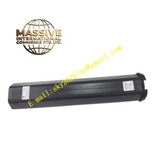
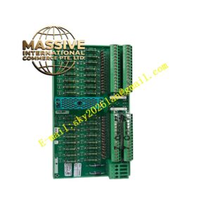
Structural Features DIN rail mount compact housing; Front panel LED indicators; Top and bottom screw terminals for safety input, output and power; Internal dual independent evaluation circuits; Mechanical interlock structure for safety relay contacts.
Working Principle Two independent safety input channels receive signals from safety devices. Internal dual monitoring circuits continuously compare signal states of both channels. If channel state mismatch, short circuit or emergency stop trigger detected, the safety relay de-energizes immediately. Positive-guided safety contacts open to cut off power of dangerous actuators. Fault state latches and holds until safety condition recovers and reset operation executes. LED indicator shows power status and fault information.
Installation Requirements Install module on standard DIN rail inside control cabinet; Safety circuit wiring uses dedicated twisted pair cable; Safety output wires connect directly to contactor coil circuit; Cabinet protective earth connection is mandatory; Separate safety wiring from power cables.
Precautions for Use Perform safety function test after every wiring modification; Do not bypass safety input channels; Verify positive guided contact wiring periodically; Use manual reset mode for emergency stop application; Do not install in environment with explosive atmosphere.