Description
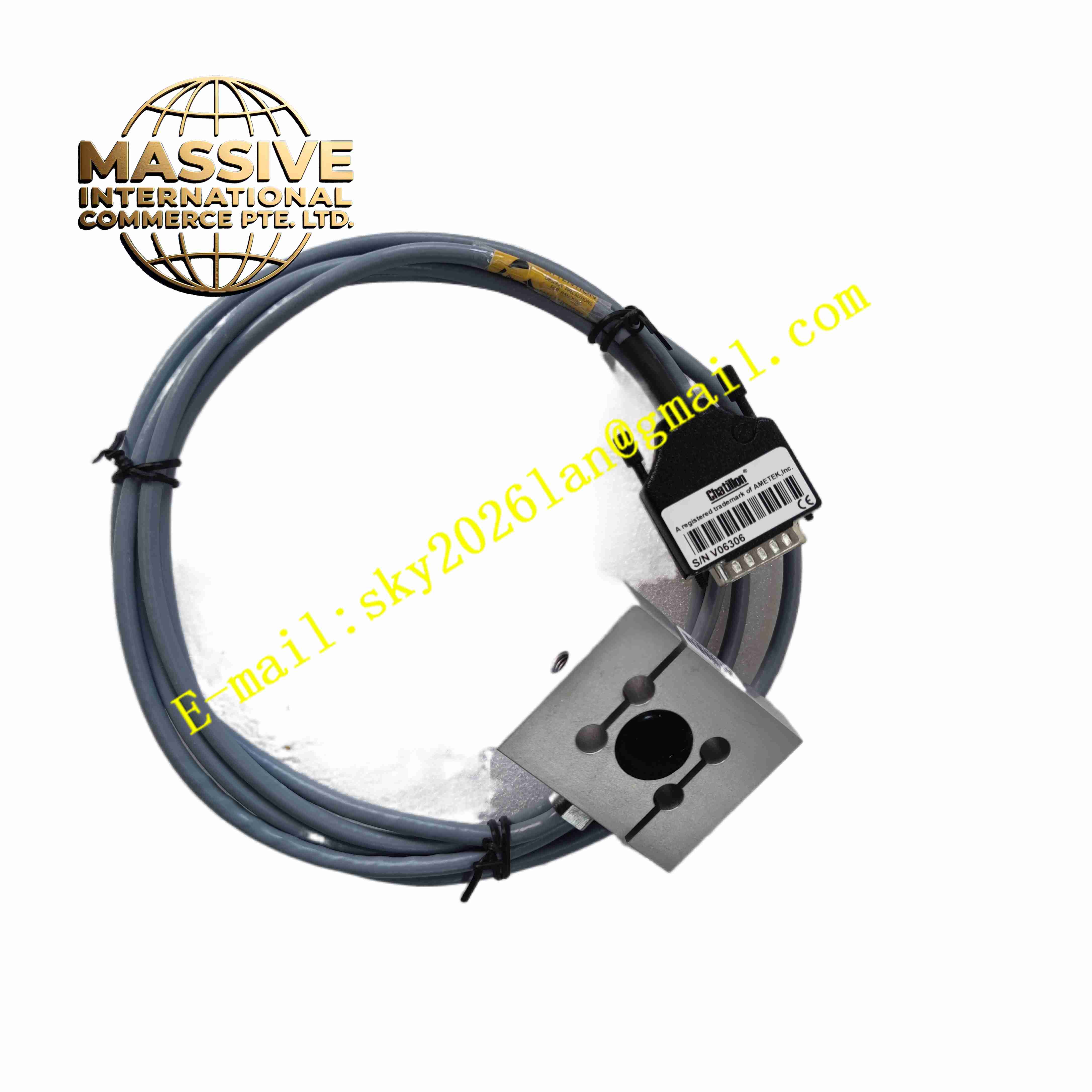
Chatillon E46-033-2
Technical Specifications
- Product Type: Strain gauge based force load cell
- Measurement Mode: Tension and compression bidirectional measurement
- Output Signal: Millivolt analog signal proportional to applied force
- Accuracy: Better than 0.2% full scale
- Overload Protection: 120% full scale overload withstand capability
- Housing Material: Stainless steel
- Operating Temperature: 5 °C to +45 °C
- Protection Class: IP54
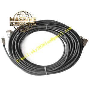
- Cable: Shielded low noise signal cable
- Mounting: Threaded mounting lugs for test fixture connection
Functional Features
- Bidirectional force measurement for tension pulling and compression pressing test.
- High precision strain gauge sensing element ensures stable measurement accuracy.
- Built-in mechanical overload stop prevents permanent damage from over force.
- Stainless steel construction resists corrosion in workshop and laboratory environment.
- Low noise shielded cable reduces electromagnetic interference impact.
- Compatible with Chatillon digital force indicators and material test frames.
- Compact size can be installed inside limited space test fixtures.
- Long-term stability with minimal zero drift after long working hours.
- Multiple adapter fittings for different test sample clamping tools.
- Calibration traceable to international force measurement standards.
Application Scenarios
- Production line product pull-off force quality inspection
- Material tensile and compression strength laboratory test
- Adhesive tape peel force test
- Spring force characteristic measurement
- Connector insertion and extraction force test
Material Composition
- Load cell body: Machined stainless steel
- Sensing element: Metal foil strain gauge bonded to elastic beam
- Internal filling material: Stabilized epoxy resin
- Cable: Shielded polyurethane insulated signal cable
- End fittings: Stainless steel threaded connectors
- Protective housing: Stainless steel outer shell
Structural Characteristics
- Cylindrical or beam-type stainless steel elastic body.
- Strain gauges bonded on the elastic beam surface, fully encapsulated by epoxy resin.
- Two threaded ends for connecting test fixtures and sample holders.
- Low noise signal cable exits from side of load cell body.
- Internal mechanical stop structure limits maximum deformation under overload.
- Sealed structure protects strain gauge from dust and moisture contamination.
Working Principle When external tension or compression force is applied to the load cell, the stainless steel elastic body produces tiny elastic deformation. The bonded strain gauges deform together and change their electrical resistance value. The Wheatstone bridge circuit converts resistance variation into millivolt analog output signal. The output signal magnitude is linearly proportional to applied force. The connected force indicator converts the analog signal into readable force value.
Installation Requirements
- Mount the load cell in axial force alignment, avoid lateral side load.
- Use matched threaded adapter and fixture to connect test sample.
- Fix signal cable with strain relief to prevent pulling force on cable joint.
- Route shielded signal cable separate from power cables.
- Perform zero tare calibration before starting each test batch.
- Keep the load cell free from impact and dropping during installation.
- Complete calibration verification before formal test execution.
Usage Notes
- Never apply lateral force or bending load to the load cell body.
- Do not exceed rated measuring range, overload causes permanent elastic damage.
- Prevent impact and dropping, mechanical shock will destroy calibration accuracy.
- Keep the load cell dry and clean, avoid corrosive liquid contact.
- Do not cut or modify the internal signal cable.
- Re-calibration is required after heavy impact or long time continuous use.
- Store in dry environment when not in use.