Description
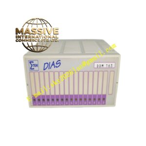
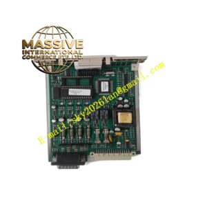
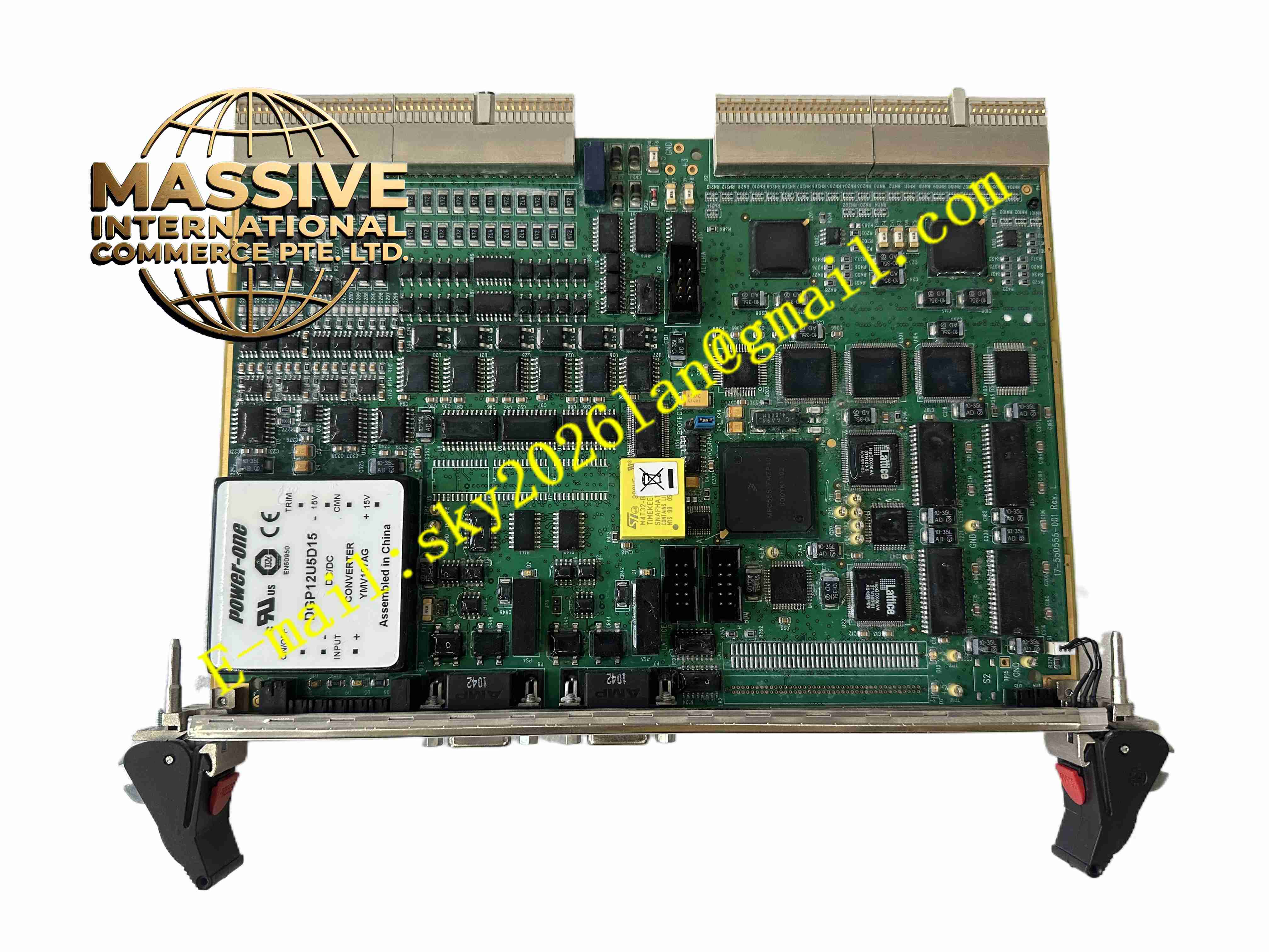
Compressor Controls Corp IOC-555-D I7-550555-001 REV
Technical Specifications
- Card type: Analog output / valve position feedback input interface card
- Output channels: 4 × 4 to 20 mA analog output
- Input channels: 4 × 4 to 20 mA valve position feedback input
- Output load: Max 750 Ω
- Input accuracy: 0.1 % FS
- Output accuracy: 0.1 % FS
- Supply: Rack backplane DC24V
- Isolation: Optically isolated between channels and backplane
- Temperature: -20 °C to +70 °C
- Storage: -40 °C to +85 °C
- Humidity: 5 % to 95 %, non-condensing
- Protection: IP20
- Installation: Eurocard plug-in
Functional Features
- 4-channel 4 to 20 mA output driving control valves and anti-surge valves
- 4-channel 4 to 20 mA valve position feedback input forming closed-loop control
- Independent optical isolation per channel
- 0.1 % high-precision analog conversion
- Output loop wire-break monitoring with real-time CPU reporting
- Front panel LEDs per channel output and input status
- Electrical isolation between backplane and field
- On-board fuse protection for output loops
- Industrial-grade components resisting vibration and EMI in compressor buildings
- Communication with CCC main CPU over backplane bus
Application Scenarios
- Centrifugal compressor anti-surge valve control output
- Natural gas transmission pipeline compressor unit control valves
- Refinery process air compressor valve control
- Chemical plant synthesis gas compressor valve position feedback
- CCC Compressor Controls system cabinet I/O cards
Materials and Construction
- Front panel: Anodized aluminum panel
- PCB: FR4 multilayer board with conformal coating
- Analog components: High-precision DAC and ADC chips
- Isolation: Optocouplers
- Passive components: Precision metal film resistors, ceramic capacitors, TVS diodes
- Connector: Gold-plated Eurocard backplane connector
- Terminals: Screw-fastened tin-plated copper terminals
Structural Features
- Eurocard plug-in structure in CCC control cabinet rack
- Front panel channel LEDs and field wiring terminals
- Board partitions between analog output, analog input, and isolation areas
- Precision analog circuits placed away from digital interference
- Card locking mechanism resisting compressor building vibration
- Metal panel shielding
Working Principle The main CPU sends 4 to 20 mA output setpoints over the backplane; the on-board DAC converts digital data to analog current through isolation to field valves. Field valve position 4 to 20 mA feedback enters terminals, is sampled by ADC, and uploaded to the main CPU over the backplane. Output loop monitoring detects current to identify wire-break faults. LEDs indicate channel status in real time.
Installation Requirements
- Insert card into rack slot with power off and ESD protection
- Use shielded twisted pair for field signal wires, single-point shield grounding
- Route 4 to 20 mA signal wires separately from power cables
- Rack grounding
- Cabinet temperature -20 °C to +70 °C
- Calibrate output and input loop accuracy after power-up
Precautions
- Do not hot-swap during online operation
- Do not short output loops; short circuits trigger protection
- Wear ESD wrist strap
- Periodically calibrate analog output accuracy
- Store spares in anti-static, moisture-proof packaging
- Verify all channels from the main control software after card replacement