Description
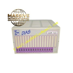
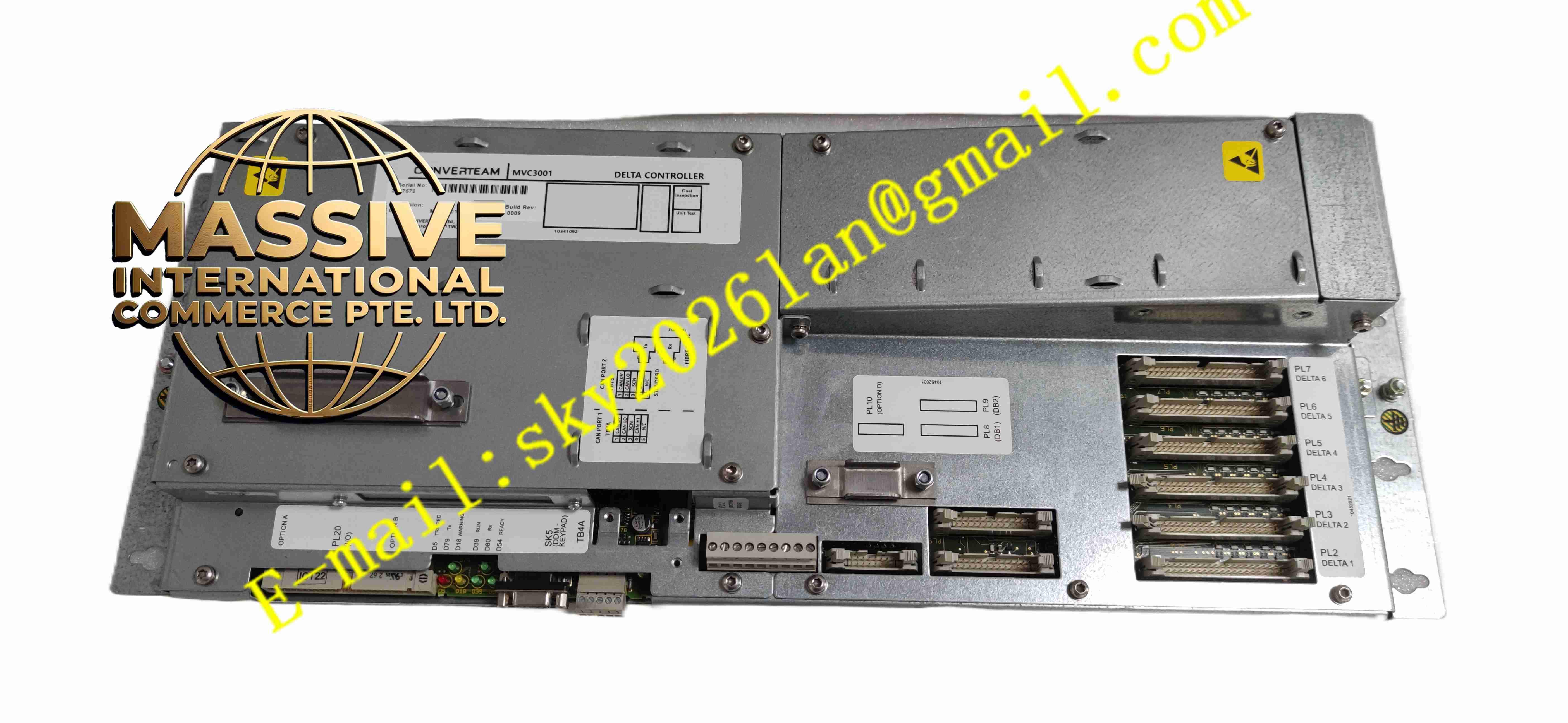
ConVerteam MVC3001-4003A
Technical Specifications: Main processor: 40MHz DSP digital signal processor Operating supply voltage: Power obtained from internal transistor bridge module of drive Working temperature range: 0℃ ~ +60℃ Storage temperature range: -40℃ ~ +85℃ Communication interfaces: RS232, RS485, CAN bus; support Modbus and ESP communication protocols Expansion interface: Reserved slots for PROFIBUS DP, CANopen and Ethernet option modules Control mode: V/F control, open-loop vector control, closed-loop flux vector control Overload capacity: 200% short-time overload capacity Protection grade: IP20 for controller unit Mounting method: Installed inside medium voltage inverter cabinet
Functional Features: High precision closed-loop and open-loop vector algorithm for AC asynchronous motor speed regulation. Real-time collection of voltage, current, temperature and speed feedback signals of power unit. Complete fault diagnosis for overcurrent, overvoltage, undervoltage, overheating and motor overload. Multiple industrial communication protocols to realize data interaction with PLC and DCS host system. Parameter local configuration through serial port and remote online diagnosis function. Support speed closed-loop control with motor encoder feedback. Built-in fault log storage to record fault time and operating parameters at fault moment.
Application Scenarios: Large fan and water pump variable speed control, metallurgy rolling mill drive system, mining conveyor equipment, cement plant main drive, large compressor speed regulation, marine power drive system, heavy industry medium voltage variable frequency drive cabinets.
Performance Parameters: Motor speed regulation range: 0 rpm to 3000 rpm Control response speed: Fast closed-loop adjustment for sudden load change. Data sampling cycle: High-speed real-time sampling of power circuit operating parameters. Continuous operation: Support 24-hour continuous heavy-duty operation. Fault response speed: Rapid trigger of protection instruction once abnormal condition detected.
Material Composition: Main substrate: FR4 high reliability industrial printed circuit board. Core components: DSP processor, high-speed AD sampling chip, communication transceiver chip, optocoupler isolation components. Front panel housing: Flame retardant PC plastic with status LED indicators. Connector terminals: PA66 flame retardant plastic and gold-plated copper alloy pins. Internal shielding: Metal shielding plate for anti-electromagnetic interference.
Structural Features: Rectangular plug-in controller board, fixed inside inverter cabinet with screw fasteners. Front panel integrates multiple LED indicator lights for power, running state and fault alarm. Internal circuit partition layout: power supply area, analog sampling area, digital computing area and communication interface area. Reserved expansion slot for additional communication protocol modules. Removable terminal blocks for internal wiring between controller and power modules.
Working Principle: After the medium voltage drive system is powered on, the controller obtains auxiliary power supply from the internal power bridge module. The DSP processor receives speed and torque setpoint commands from upper control system via communication port. It collects real-time voltage, current and motor encoder feedback signals, runs vector control algorithm, and outputs PWM drive instruction to IGBT power units. The controller continuously monitors operating parameters of power circuit. When parameter exceeds threshold value, the controller immediately outputs protection signal to cut off power output and record fault information.
Installation Requirements: Install the controller board in designated compartment inside ALSPA MV3000 medium voltage inverter cabinet. Fix the board with mounting screws to avoid mechanical vibration loosening. Separate analog signal cables, digital communication cables and high-voltage power cables. Connect cabinet protective earth ground to the designated grounding terminal of controller. Reserve sufficient ventilation space around controller board for heat dissipation. Complete parameter configuration and motor identification before commissioning.
Usage Notes: Cut off all high voltage and auxiliary power supply of inverter cabinet before disassembly and wiring. Do not operate the cabinet door when medium voltage power is on. Backup all drive parameters before replacing the controller module. Prevent dust and conductive particles from accumulating on circuit board surface. Do not modify internal circuit components of controller arbitrarily. Regularly check terminal wiring tightness and LED operating status during equipment maintenance.