Description
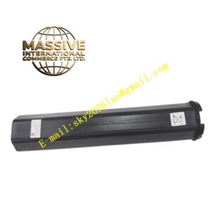
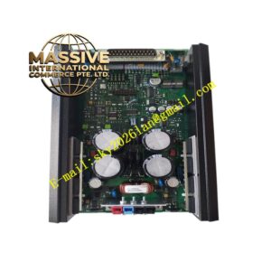
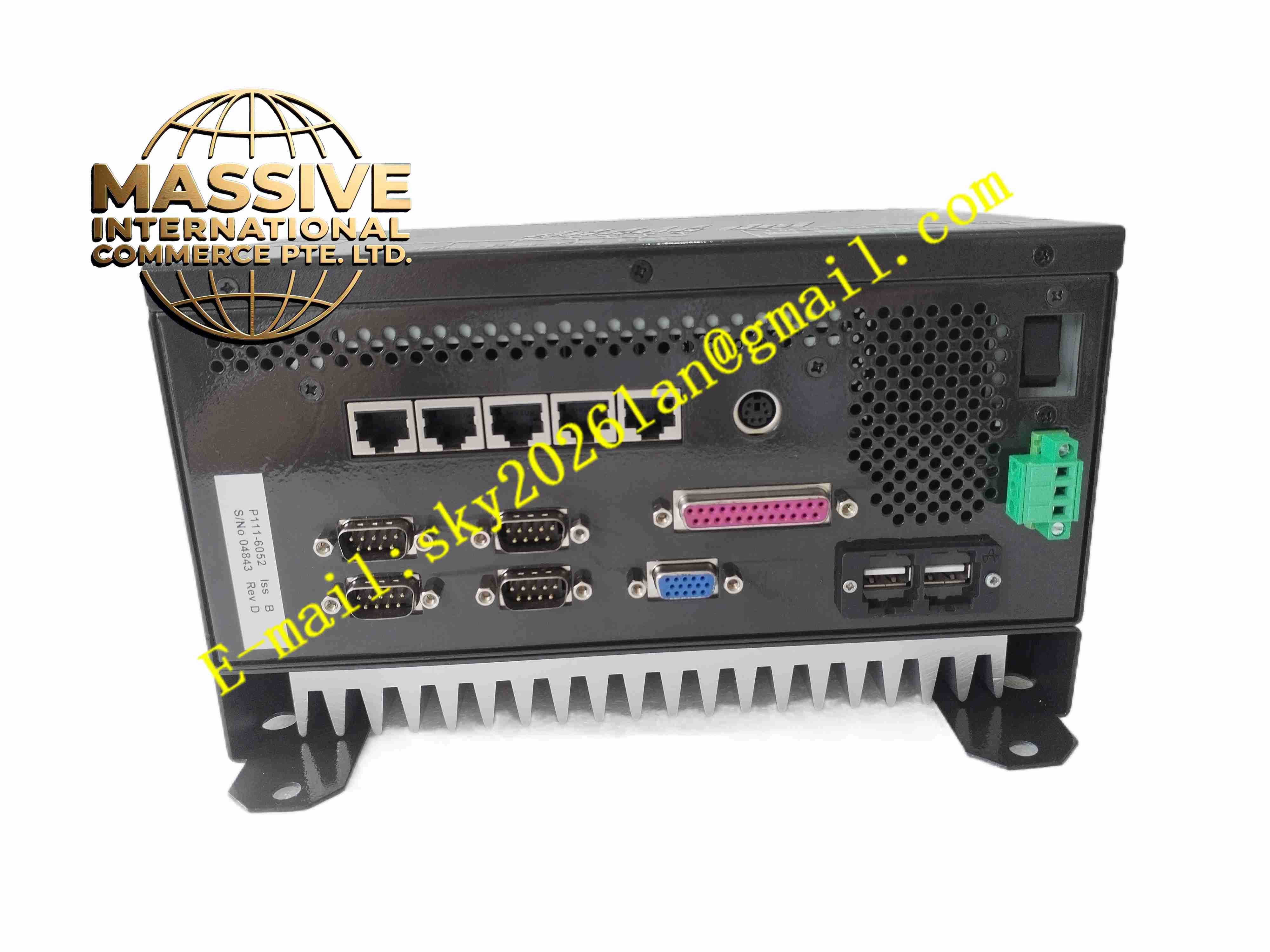
CONVERTEAM P111-6052
Technical Specifications: Product type: Power converter control interface printed circuit board Signal type: Analog current/voltage sampling, digital trigger pulse, binary fault I/O Backplane interface: Converteam proprietary internal system bus Power supply: Low voltage DC power supplied from converter control chassis Operating temperature range: 0℃ ~ +60℃ Storage temperature range: -40℃ ~ +85℃ Relative humidity: 5% to 95%, non-condensing Form factor: Plug-in rack card Protection grade: IP20 when installed inside converter cabinet
Functional Features: Analog sampling of voltage and current feedback signals from converter power stage. Generate trigger pulse signal for power semiconductor switching devices. Execute hardware overcurrent and overvoltage fast protection logic. Bidirectional communication with main controller via internal backplane bus. Collect binary fault feedback signals from power unit and cooling system. Transmit converter operating status and fault code to main control board. Built-in hardware fault latch for critical power circuit protection events. Front panel LED indicators for power status and fault alarm.
Application Scenarios: Large synchronous motor excitation control, medium voltage variable frequency drive cabinet, hydroelectric generator excitation system, metallurgy rolling mill main drive converter, wind turbine power converter, large pump and fan medium voltage drive system.
Performance Parameters: Fast hardware protection response speed for power stage overcurrent fault. High precision sampling of analog current and voltage feedback signal. Stable pulse signal transmission under strong electromagnetic interference environment. Continuous operation: 24 hours uninterrupted operation inside power converter cabinet. Fault latch function retains fault state until manual reset.
Material Composition: PCB substrate: Multi-layer high TG FR4 glass fiber epoxy printed circuit board with conformal coating. Core components: Analog sampling IC, pulse drive chip, logic processor, surge suppression diode array, optocoupler isolation device. Front panel: Black flame retardant ABS plastic panel with silk screen and LED windows. Backplane connector: Gold plated copper alloy contact pins with anti-oxidation treatment. Signal terminal connector: PA66 flame retardant plastic connector with nickel plated contacts.
Structural Features: Standard single width plug-in card structure matching Converteam control rack. Front panel with status LED indicators and board mechanical locking latch. Internal circuit layout divided into analog sampling area, pulse output area, logic processing area and backplane bus interface area. Optocoupler isolation between high power side signal and low voltage control logic circuit. Conformal coating covers entire PCB surface for dust and moisture protection. Internal ground separation between analog signal ground and digital logic ground.
Working Principle: Low voltage DC power is supplied to board through rack backplane. Analog voltage and current feedback signals from power unit enter the board via signal terminals. Sampling circuit converts raw analog signal into digital value for logic processor. Processor generates trigger pulse signal to control power semiconductor switch operation. Hardware protection circuit continuously monitors sampled current and voltage value. When overcurrent or overvoltage exceeds threshold, protection circuit immediately blocks trigger pulse and latches fault status. Fault signal is transmitted to main controller board via backplane bus, and front panel fault LED lights up.
Installation Requirements: Cut off converter cabinet main power and control power before inserting or removing board. Insert P111-6052 board into designated rack slot and lock front panel latch. Connect external voltage/current feedback signal cables and binary fault wiring to signal connectors. Download converter control parameters and protection threshold configuration via engineering software. Ensure converter cabinet protective earth ground connection is reliable. Separate weak control signal cables from high power busbar and high voltage cables. Reserve ventilation clearance around board for heat dissipation.
Usage Notes: Backup converter parameter configuration before board replacement. Wear anti-static wristband during board handling. Do not apply high voltage signal to low voltage sampling terminals. Regularly inspect connector tightness and LED indicator status. Do not scratch PCB conformal coating surface. Do not operate board outside rated temperature and humidity range. Prevent conductive dust accumulation on PCB and connector pins.