Description
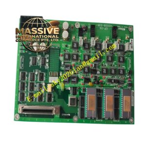
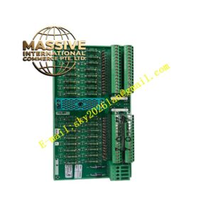
COOPER GHG122
Technical Specifications
- Product Type: Intrinsically safe switching amplifier, safety barrier
- Power Supply: 20-250 V AC / 20-60 V DC
- Intrinsic Safety Certificate: ATEX, IECEx
- Isolation Voltage: 2.5 kV AC
- Input Type: Dry contact / proximity switch signal from hazardous area
- Output Type: Relay contact or transistor switch output for safe side
- Protection Rating: IP20 for cabinet-mounted unit
- Operating Temperature: -20 °C to +60 °C
- Storage Temperature: -30 °C to +70 °C
- Relative Humidity: 5 % to 95 %, non-condensing
- Mounting: Standard 35 mm DIN rail mounting
- Net Weight: 0.22 kg
Functional Features
- Intrinsic safety energy limiting circuit restricts voltage and current supplied to field hazardous circuits.
- Galvanic isolation separates hazardous zone field wiring and safe control cabinet circuits.
- Signal amplification processes weak contact signals from field proximity switches and limit switches.
- Built-in short-circuit and wire-break diagnostic monitoring for field sensor loops.
- LED indicators display power status, input signal state and fault alarm.
- Reverse polarity protection prevents damage from incorrect power wiring.
- Compact single-width DIN rail housing saves cabinet installation space.
- Multiple variants support different input-output transfer modes for various field devices.
- Continuous self-test runs during operation to verify internal safety circuit integrity.
- Compliant with ATEX and IECEx standards for gas group hazardous locations.
Application Scenarios
- Petrochemical plant hazardous zone limit switch and proximity signal isolation
- Refinery explosive area safety interlock signal transmission
- Offshore platform intrinsic safety field signal conditioning
- Chemical reactor flammable vapor zone discrete signal collection
- Coal mine auxiliary plant explosion-proof switching signal interface
Material Composition
- Housing: Flame-retardant polycarbonate plastic
- Main PCB: FR4 printed circuit board with conformal coating
- Safety components: Zener diodes, current limiting resistors for intrinsic safety
- Relay components: Industrial low-power signal relays
- Terminal blocks: Tin-plated copper alloy screw terminals
- Isolation components: High voltage optocoupler isolation chips
Structural Characteristics
- Slim rectangular DIN rail enclosure structure.
- Front panel with LED status indicators for power, signal and fault.
- Rear screw terminal blocks for field hazardous wiring and safe-side control wiring.
- Internal circuit layout strictly segregates intrinsically safe circuit and non-safe power circuit.
- Mechanical keying prevents incorrect wiring between safe and hazardous terminals.
- Passive convection cooling without fan components.
Working Principle Field contact signal from explosive zone enters GHG122 intrinsically safe terminals. Internal energy limiting circuit caps voltage and current on field side to avoid spark generation. The signal conditioning circuit amplifies and stabilizes the switching signal. Galvanic isolation barrier blocks high potential difference between hazardous and safe side. Processed switching signal is transmitted via relay or transistor output to PLC input module. Diagnostic circuit continuously monitors field loop impedance and triggers fault indication for open or short circuit.
Installation Requirements
- Mount GHG122 on 35 mm DIN rail inside non-hazardous control cabinet only.
- Use shielded twisted pair cable for field sensor wiring routed into hazardous area.
- Separate intrinsically safe wiring from non-safe power cables in cable trays.
- Complete protective earth connection to cabinet ground bar.
- Verify intrinsic safety loop calculation matches field sensor parameters before commissioning.
- Perform contact signal test and fault simulation test after wiring completion.
- Confirm ATEX installation rules for cable entry and sealing in hazardous zone.
Usage Notes
- Do not modify internal safety components of the barrier unit.
- Do not connect non-intrinsically safe power to field-side terminals.
- Keep cabinet environment free of corrosive gas and conductive dust.
- Inspect terminal screw tightness periodically under vibration conditions.
- Disconnect power before modifying wiring.
- Use anti-static wristband when handling spare modules.
- Replace unit immediately when permanent circuit damage occurs.