Description
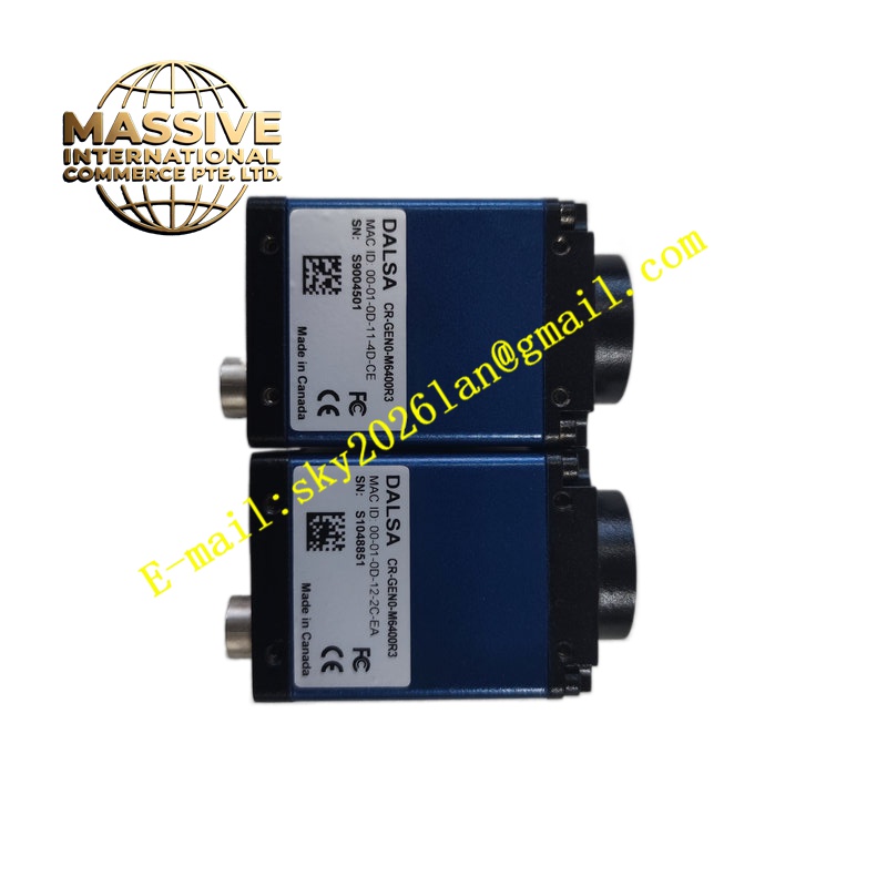
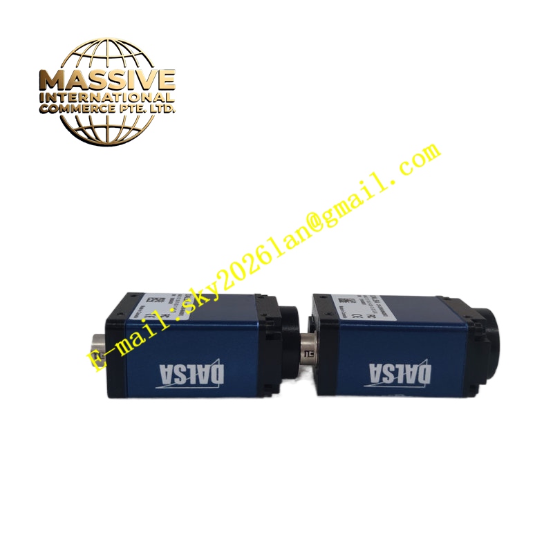
DALSA CR-GEN0-M6400R3
Technical Specifications
Brand: Teledyne DALSA
Product Model: CR-GEN0-M6400R3
Product Type: Industrial Line Scan Camera
Sensor Type: High-performance CCD or CMOS linear image sensor (specific type depends on configuration)
Resolution: High-resolution linear array for detailed image capture
Interface: GigE Vision or Camera Link for high-speed data transmission
Frame Rate / Line Rate: High line scan rate suitable for fast-moving production lines
Operating Temperature: 0°C to +50°C
Storage Temperature: -20°C to +60°C
Relative Humidity: 5% to 95% (non-condensing)
Dimensions: 64mm × 64mm × 30mm
Power Supply: Standard industrial DC voltage (typically 12V or 24V DC)
Certification Standards: CE, RoHS compliant
Functional Features
High-Resolution Imaging: Delivers sharp, detailed images for precise defect detection and measurement
High-Speed Acquisition: Fast line scan rates enable inspection of rapidly moving products
Robust Industrial Design: Built to withstand vibration, temperature fluctuations, and humidity in factory environments
Flexible Integration: Compatible with standard machine vision interfaces and software platforms
Advanced Image Processing: Supports on-camera image processing functions including filtering, enhancement, and analysis
Multiple Lens Options: Compatible with various industrial lenses for different field-of-view and magnification requirements
Programmable Control: Allows configuration of exposure, gain, trigger mode, and other parameters via software
Real-Time Data Output: Transmits image data directly to vision processing systems for immediate analysis
Flat-Field Correction: Built-in FFC for uniform image quality across the entire sensor width
Multi-Region of Interest: Supports configurable ROI for targeted inspection and reduced data bandwidth
Application Scenarios
Web Inspection: Continuous inspection of paper, film, foil, textile, and nonwoven materials for defects
Print Quality Control: Detection of print defects, color registration errors, and missing characters in packaging and label printing
Semiconductor Manufacturing: Wafer inspection, die sorting, and component verification
Electronics Assembly: PCB inspection, component placement verification, and solder joint quality control
Food and Beverage: Packaging inspection, label verification, and product sorting
Pharmaceutical: Blister pack inspection, label reading, and capsule sorting
Automotive: Surface inspection of metal sheets, paint quality control, and component verification
Solar Panel Production: Cell inspection, crack detection, and quality grading
Performance Parameters
Sensor Resolution: High pixel count linear array for fine detail capture
Line Rate: Capable of scanning thousands of lines per second for high-throughput inspection
Signal-to-Noise Ratio: High SNR for clean images in varying lighting conditions
Dynamic Range: Wide dynamic range to capture details in both bright and dark areas
Quantum Efficiency: High QE for good sensitivity across the spectral range
Data Throughput: High-speed interface ensures no data loss during continuous scanning
Trigger Response: Fast trigger response for precise synchronization with production line motion
Image Uniformity: Excellent pixel-to-pixel uniformity for consistent measurement accuracy
Material Composition
Industrial-grade aluminum alloy housing for durability and heat dissipation, high-quality optical glass sensor window, precision-machined internal components, surface-mounted electronic components on multi-layer PCB, gold-plated connector contacts for reliable signal transmission, flame-retardant materials compliant with UL94 standards
Structural Features
Compact 64mm × 64mm × 30mm form factor for space-constrained installations, robust aluminum enclosure with integrated heat dissipation features, standardized mounting holes for secure installation, industrial-grade connector for data and power, status LEDs for power and trigger indication, protective sensor window with anti-reflective coating, sealed housing to resist dust and moisture ingress, modular design for easy integration into vision systems
Working Principle
The CR-GEN0-M6400R3 operates as a line scan camera, capturing images one line at a time rather than a full frame. As the target object moves past the camera (or the camera moves past the object), the linear image sensor continuously acquires successive lines of pixel data. Each line is triggered either by an external encoder signal synchronized with the motion or by an internal timer. The captured analog signal from each pixel is converted to digital data by an on-board analog-to-digital converter (ADC). The digital image data is then processed through on-camera electronics for tasks such as flat-field correction, gain adjustment, and black level calibration. The processed data is transmitted via GigE Vision or Camera Link interface to a host computer or vision processing system, where successive lines are assembled into a complete two-dimensional image for analysis, defect detection, measurement, or classification. The camera’s trigger input ensures precise synchronization with the motion of the inspected material, preventing image distortion.
Installation Requirements
Mount the camera securely using the provided mounting holes, ensuring stable positioning relative to the inspection target
Align the camera perpendicular to the moving web or product surface for uniform image capture
Install an appropriate industrial lens based on the required field of view, working distance, and resolution
Connect the camera to a compatible power supply (typically 12V or 24V DC) using proper cabling
Connect the data interface (GigE Vision or Camera Link) to the host computer or frame grabber
If using external triggering, connect the encoder or trigger signal to the camera’s trigger input
Ensure adequate lighting is installed to provide uniform illumination across the inspection area
Configure camera parameters (exposure time, gain, line rate, trigger mode) using DALSA’s Sapera LT or compatible software
Verify proper grounding to minimize electrical noise and ensure signal integrity
Usage Precautions
Do not expose the camera sensor to direct intense light sources such as lasers or bright sunlight without proper filtering
Ensure the operating temperature remains within the specified 0°C to +50°C range
Keep the sensor window clean and free of dust, oil, or debris; clean with appropriate optical cleaning materials
Verify that the power supply voltage is within the specified range to prevent damage
Use shielded cables for data and trigger connections to minimize electromagnetic interference
Ensure proper ventilation around the camera to maintain optimal operating temperature
Do not attempt to disassemble or repair the camera internally; return to authorized service centers for maintenance
Back up camera configuration settings before making changes
Regularly verify image quality and calibration to maintain inspection accuracy
Handle the camera with care during installation to avoid mechanical shock or vibration damage