Description
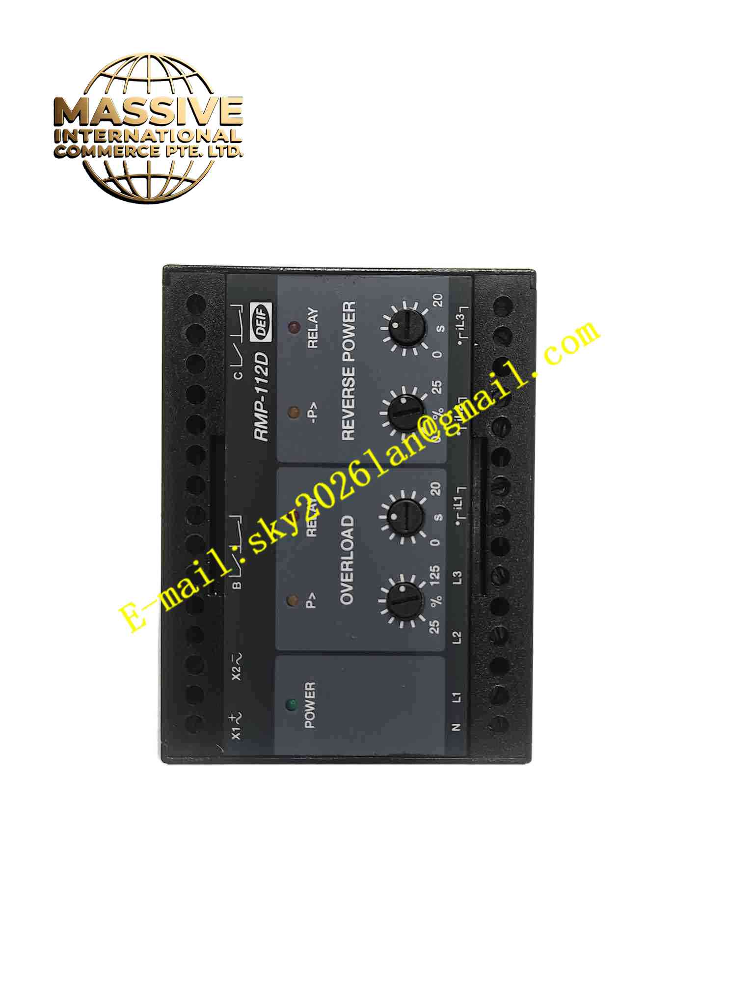
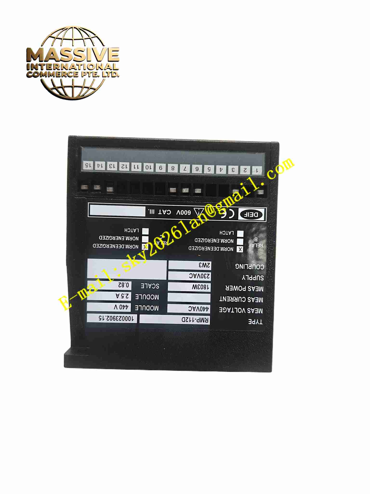
DEIF RMP-112D
Technical Specifications
- Product type: Generator protection and control relay
- Measurement: 3 phase voltage, 3 phase current, frequency, power
- CT input: 1A or 5A selectable
- PT input: 100V to 400V
- Supply: DC24V / AC110V to 230V wide range
- Communication: RS485 Modbus RTU
- Relay output: Multiple programmable relay contacts
- Operating temperature: -25 °C to +70 °C
- Storage temperature: -40 °C to +85 °C
- Humidity: 5% to 95%, non-condensing
- Protection rating: IP20 for rear terminals, IP40 for front panel
- Installation: Panel cutout mounting
- Display: LCD graphic display with pushbuttons
Functional Features
- Comprehensive generator electrical protection functions
- Three phase voltage and current measurement
- Real power, reactive power and frequency calculation
- Generator paralleling and synchronisation control
- Load sharing management for multiple gensets
- Event recording and fault waveform capture
- Modbus RTU communication for SCADA connection
- Front panel local parameter setting and status viewing
- Programmable relay output logic
- Wide temperature range for marine and industrial environments
Application Scenarios
- Marine diesel generator protection and control
- Onsite backup generator in data centre
- Captive power plant generator paralleling
- Offshore platform genset control
- Factory emergency power system
Materials and Construction
- Front panel: Flame retardant polycarbonate plastic
- PCB: FR4 board with conformal coating
- Current and voltage sampling: Precision voltage divider and current transformers
- Relays: Sealed industrial control relays
- Pushbuttons: Sealed tactile buttons
- Housing: Flame retardant plastic enclosure
Structural Features
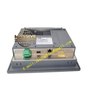
- Rectangular panel mount housing
- Front panel LCD screen and function pushbuttons
- Rear terminal blocks for CT, PT, power supply and communication
- Internal sampling circuit, CPU and relay output assembly
- Removable screw terminal blocks
- Panel gasket to prevent dust ingress at cutout gap
Working Principle Three phase voltage and current signals pass through internal sampling components. The onboard CPU samples these signals and calculates electrical parameters continuously. Measured values compare against user defined protection setpoints. When parameters exceed threshold, the relay activates trip contact to open generator breaker. Synchronisation logic matches voltage, frequency and phase angle before closing breaker for paralleling. Modbus port uploads measured data and fault records to supervisory system.
Installation Requirements
- Install relay through panel cutout and secure with mounting clips
- Wire CT secondary circuit and PT secondary circuit to rear terminals
- Connect breaker control wiring and power supply
- Route RS485 shielded twisted pair cable for Modbus communication
- Maintain ambient temperature between -25 °C and +70 °C
- Set CT ratio, PT ratio and protection parameters after power on
- Connect protective earth to relay housing
Precautions
- CT secondary circuit must not open during operation
- PT secondary circuit must not experience short circuit
- Protection setpoints must match generator nameplate rating
- Perform protection function test during commissioning
- RS485 bus termination resistor installed at bus endpoints
- Store spare relays in dry environment
- Check event log regularly for generator abnormal records
- Isolate CT and PT wiring before relay removal