Description
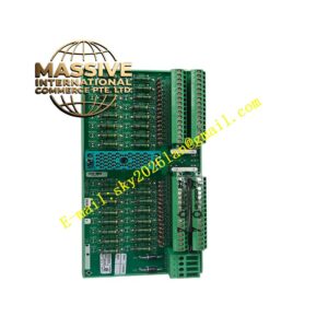
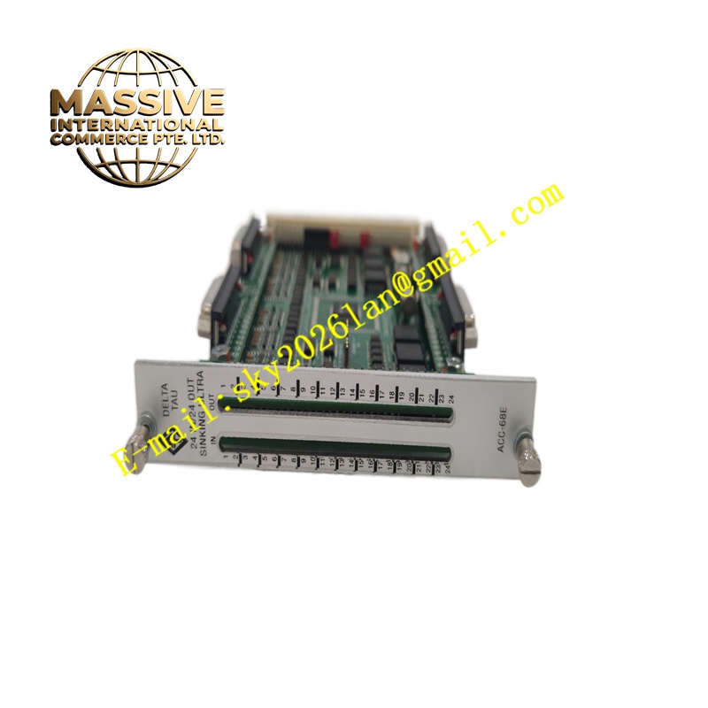
Delta Tau ACC-68E
Technical Specifications 48 digital input channels and 20 digital output channels; input signal type supports 5V, 12V and 24V logic levels; outputs feature sinking and sourcing configurable types; opto-isolation applied to each I/O channel; maximum input frequency 1MHz; output switching speed 200ns; power supply sourced from PMAC backplane 5V DC; operating temperature range -20°C to +70°C; storage temperature -40°C to +85°C; relative humidity 5% to 95% non-condensing.
Functional Features Receives discrete trigger signals from limit switches, home sensors, proximity sensors and safety interlock devices. Generates high-speed digital output pulses to trigger valves, relays, lights and other auxiliary machine actuators. Synchronizes I/O actions with motion trajectories for electronic cam and position-latched trigger functions. Provides channel-by-channel fault diagnosis for open circuit and abnormal voltage states. Transmits I/O status data to the PMAC main processor over the expansion bus. Supports software configuration of input polarity and output logic state.
Application Scenarios Automated assembly equipment, semiconductor handling machines, packaging automation lines, laser processing systems, test and measurement automation stations, multi-axis CNC auxiliary signal control.
Performance Parameters Hardware-level signal latching independent of main processor cycle; high noise rejection through optoelectronic isolation; consistent timing synchronization with servo interpolation cycle; stable signal transmission under continuous high-speed triggering.
Material Composition Main printed circuit board adopts FR-4 flame-retardant multilayer substrate; optocoupler isolation chips and digital logic chips are industrial wide-temperature semiconductors; edge connectors use gold-plated copper alloy contacts; passive resistors and capacitors use high-stability industrial grade components; signal terminal connectors use nickel-plated copper contact springs.
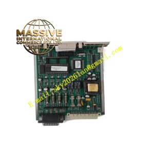
Structural Characteristics Rectangular plug-in expansion board form factor matching PMAC carrier chassis slots. Multiple pin header connectors on the board edge for external field wiring. Onboard LED indicators display power status and signal activity of each bank of I/O channels. Mounting holes fix the board to the chassis or PMAC carrier board. Expansion bus connector at the rear side mates with the PMAC main controller.
Working Principle External field sensor signals enter the opto-isolation circuit of each input channel, converting field-side voltage signals into logic signals recognizable by the onboard logic chip. The logic chip transmits input status to the PMAC main controller via the expansion bus. When the motion controller issues output commands, the onboard drive circuits activate the corresponding output channels to drive external loads. All signal sampling and output updates synchronize with the PMAC servo loop timing.
Installation Requirements Cut off the power supply of the PMAC chassis before board installation. Insert the board into the designated expansion slot on the PMAC carrier and secure mounting screws. Wire field sensors and actuators to the external terminal connectors with shielded cables. Configure I/O polarity and mapping rules in the PMAC programming software. Test input capture and output triggering functions after power restoration.
Precautions for Use Follow electrostatic discharge protection procedures when touching the bare printed circuit board. Separate I/O signal cables from high-power servo motor cables to avoid electromagnetic interference. Do not connect loads exceeding the rated current of each digital output channel. Verify isolation integrity after long-term cabinet operation.