Description
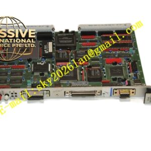
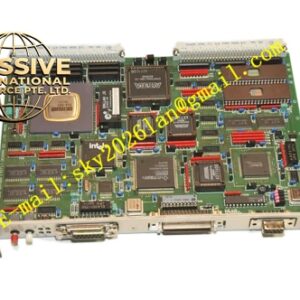
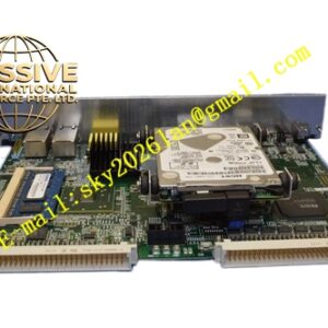
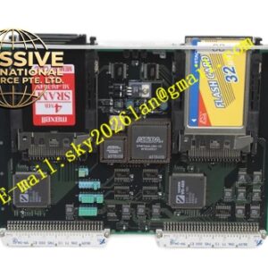
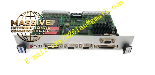
Densan DVE‑486‑20A (9295A)
Technical Specifications: Bus specification: VME bus Output signal form: analog voltage, analog current Digital‑to‑analog conversion resolution: 16‑bit Isolation withstand voltage: 1500 VAC between field side and VME bus side Operating temperature: 0 ℃ to 55 ℃ Storage temperature: -40 ℃ to 85 ℃ Relative humidity: 5%‑95% non‑condensing Mounting way: 6U VME plug‑in module Protection grade: IP20
Functional Features: Multi‑channel isolated analog output. 16‑bit high‑precision DAC conversion circuit. Each channel supports programmable output range configuration. Front‑panel LED indicators for power supply and fault alarm. Built‑in short‑circuit protection for output loop. Hardware automatic calibration function. VME bus register access for output setting and status reading. Power‑on self‑diagnosis function.
Application Scenarios: Semiconductor equipment analog actuator control, industrial precision valve adjustment control, automated test equipment analog signal source output, pilot plant process control rack, new‑energy test bench analog drive control, precision automation equipment closed‑loop adjustment system.
Performance Parameters: DAC settling time: less than 200 μs Output accuracy: ±0.05% full scale Vibration resistance: 10 Hz‑150 Hz, 0.5 g Shock resistance: 10 g peak acceleration, 11 ms duration MTBF value: 191000 hours
Material Composition: Front‑panel adopts oxidation‑resistant aluminum alloy. Main printed circuit board uses FR‑4 high‑Tg glass‑fiber epoxy substrate. Backplane connector contacts use gold‑plated copper alloy. DAC chip and isolation components adopt industrial‑grade devices. Fastening hardware uses nickel‑plated steel.
Structural Features: 6U VME plug‑in board structure. Metal front panel fitted with locking handles and status LED indicators. Rear multi‑pin gold‑plated connector mates with VME rack backplane. Internal circuit divides analog output region and digital bus logic region, with isolation barrier in‑between. Output signal path adopts anti‑interference wiring layout. Ventilation openings reserved for passive heat dissipation.
Working Principle: VME main controller writes target output digital value into board register via VME backplane bus. Digital signal transmits to DAC conversion chip after isolation processing. DAC converts digital quantity into standard analog voltage or current signal. Analog signal passes through driving circuit and outputs toward field actuator. On‑board protection circuit takes effect when output loop short‑circuit occurs, and fault status can be read through VME bus.
Installation Requirements: Insert module to specified slot of VME rack, lock front‑panel screws. Guarantee adequate heat‑dissipation ventilation space inside cabinet. Use shielded twisted‑pair cable for analog output signal wiring. Analog signal cables must keep distance from high‑power cables. Disconnect rack total power before installing or removing the board. Complete static elimination before contacting circuit board.
Precautions for Use: Do not make output channel bear load exceeding specified range. Wear anti‑static wristband during maintenance work. Keep ventilation openings clean without dust accumulation. Forbid installation in corrosive gas environment. Perform periodic hardware calibration according to maintenance manual. Inspect cable shielding grounding condition regularly.