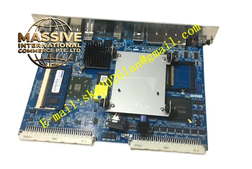
Description
Densan DVEP7447‑50A
Technical Specifications: Bus compliance: VME ANSI/IEEE 1014, supports VME master and slave mode Form factor: 6U single‑slot VME plug‑in module Power supply input: +5VDC, ±12VDC supplied from VME backplane On‑board memory: Industrial grade soldered RAM and compact flash storage slot Network interface: Multiple RJ45 Ethernet ports deployed on front panel External expansion interface: Supports external storage and debug serial port Operating temperature: 0 ℃ to 55 ℃ Storage temperature: -40 ℃ to 85 ℃ Relative humidity: 5% to 95% non‑condensing Protection grade: IP20 Backplane connector: DIN 41612 J1 / J2 high‑density gold‑plated connector
Functional Features: Acts as VME bus master controller to complete read‑write access toward every VME‑slave I/O module. Multi‑port independent Ethernet communication for data interaction with remote host system. On‑board large‑capacity non‑volatile compact flash storage for operating system, application firmware and process configuration parameter preservation. Hardware watchdog timer achieves automatic system reset when program execution runs away. Front‑panel multi‑group LED indicator lamps display power status, CPU running status, network link activity and fault alarm information. Comprehensive power‑on hardware self‑diagnosis covers CPU core, memory unit, bus interface and network circuit. Built‑in multi‑stage EMC filtering circuit suppresses industrial‑site electromagnetic interference. Supports VME bus interrupt receiving and interrupt output forwarding function. Provides dedicated debug serial port for system maintenance and troubleshooting.
Application Scenarios: Semiconductor wafer fabrication equipment main control cabinet, high‑precision automated test equipment host unit, large‑scale VME‑based factory automation control rack, special‑purpose industrial real‑time processing equipment, electronic component production line core controller, equipment renovation replacement project for original DVE‑P7447‑50 series CPU hardware.
Performance Parameters: VME bus maximum data transmission throughput reaches 42MB/s Hardware watchdog trigger time range configurable from 10ms up to 2 seconds Ethernet communication rate supports 10/100Mbps adaptive negotiation Vibration resistance: 10Hz‑150Hz, constant amplitude 0.5g Shock resistance: 10g peak acceleration, 11ms pulse duration MTBF value: 181000 hours under cabinet forced‑air cooling environment
Material Composition: Front panel adopts high‑strength oxidation‑resistant extruded aluminum alloy with matte surface anodizing treatment. Main printed circuit board applies high‑Tg FR‑4 glass‑fiber epoxy substrate complying with UL94‑V0 flame retardant specification. Backplane connector contact pins adopt hard gold‑plated copper‑alloy material. Core CPU chip, memory particles and network controller components adopt full industrial temperature grade electronic devices. Heat dissipation assembly consists of metal aluminum heat sink and fixing fasteners. All soldering components follow industrial lead‑free process standard. Fastening hardware includes nickel‑plated carbon‑steel screws and ejector latch assemblies.
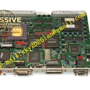
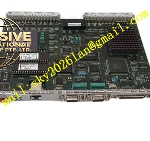
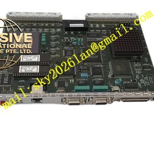
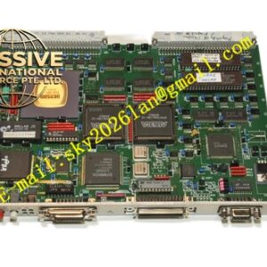
Structural Features: Standard 6U double‑height single‑slot VME plug‑in mechanical structure. Metal front panel is equipped with locking ejector handles, multiple RJ45 network jacks, debug serial port and array of status LED indicators. Rear side installs double‑row DIN41612 high‑density gold‑plated connector for reliable connection with VME rack backplane. Internal printed circuit board implements strict circuit zoning layout, divides CPU core computing area, memory storage area, VME bus interface area and network signal processing area. Large area aluminum heat sink is fixed above core processor chip for active heat conduction. Mass decoupling capacitors distribute across every functional circuit block to stabilize power‑supply ripple. Ventilation cutouts are reserved on front panel and PCB vacant region to support cabinet forced‑air convection heat dissipation. Independent shielding routing processing for high‑speed network signal traces.
Working Principle: After VME rack completes power‑on sequence, DVEP7447‑50A executes hardware power‑on self‑diagnosis routine. CPU core completes initialization of on‑board memory, storage unit, VME bus controller and multi‑port network chip. Operating system and user application firmware load from compact flash storage into on‑board RAM for execution. As VME bus master controller, this board sends address and control signals through backplane connector, reads status data from each slave‑side VME I/O module and writes output control commands toward corresponding hardware modules. Network interfaces on front panel establish TCP/IP communication link with upper‑level host system, upload real‑time process data and receive remote configuration instructions. Hardware watchdog circuit continuously monitors program operation status, triggers full‑module hardware reset once abnormal program execution is detected. Front‑panel LED lamps reflect real‑time power supply condition, operating state, network link status and fault alarm events. All hardware fault codes can be read through debug serial port or VME‑mapped status registers.
Installation Requirements: Insert DVEP7447‑50A module fully into designated empty slot of standard 6U VME rack chassis. Push dual ejector handles into fully locked position and tighten front‑panel mounting screws to guarantee stable mechanical contact of backplane connector. Maintain unobstructed airflow path inside control cabinet, ensure cooling wind passes through board heat‑sink assembly. Deploy Cat5e or higher‑grade shielded twisted‑pair cables for all front‑panel network wiring. Keep network signal cables maintain sufficient physical separation away from high‑current power cables and motor drive cables. Disconnect total rack main power supply before inserting or extracting this CPU circuit board. Operators must complete static electricity discharge procedure by touching grounded metal cabinet surface before touching bare printed‑circuit‑board surface. Do not plug or unplug compact‑flash storage device while system remains powered.
Precautions for Use: Do not apply voltage exceeding VME backplane rated specification onto board power‑supply pins. Wear anti‑static wristband during all maintenance, inspection and component replacement operations. Keep front‑panel ventilation openings and heat‑sink surface clean without dust and fiber accumulation. Do not deploy this hardware inside environment containing corrosive vapor, conductive dust or heavy oil mist. Inspect front‑panel screw tightness, ejector latch condition and backplane connector contact performance during regular equipment maintenance cycles. Back‑up complete operating system, firmware and application configuration files before board replacement. Avoid physical impact to front‑panel RJ45 network ports. Execute orderly system shutdown procedure before cutting off rack power supply.