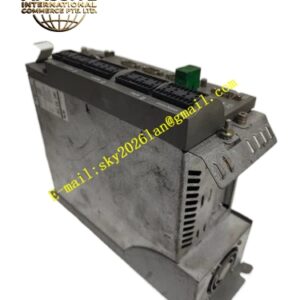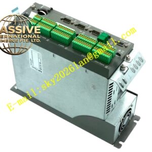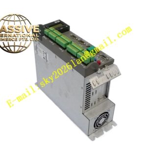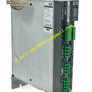
Description
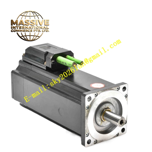
ELAU ISH070‑60011‑0‑0‑00‑00‑00‑00
Technical Specifications: DC‑link input voltage maximum 680 VDC, control power supply 24 VDC, rated speed 6000 rpm, continuous stall torque 1.1 Nm, peak torque 3.5 Nm, frame flange dimension 70 mm, shaft diameter 14 mm, integrated Hiperface absolute encoder, insulation class F, IP65 protection rating for motor part, IP50 for upper integrated drive housing, continuous input current 1.55 A, control current 0.7 A, no built‑in holding brake, net weight 3.0 kg.
Functional Features: Highly integrated structure combines motor body and servo drive, reduces cabinet internal drive installation space, SERCOS III bus interface for real‑time motion command receiving, local closed‑loop position‑speed‑current control calculation, multi‑layer hardware fault detection and diagnostic function, absolute encoder retains position information after power‑loss, built‑in winding thermal monitoring sensor, distributed wiring reduces cabinet cable quantity.
Application Scenarios: Compact packaging machine auxiliary motion axes, electronic component assembly equipment, small‑size automated handling mechanisms, high‑speed positioning axes of printing equipment, light‑load multi‑axis distributed automation production lines.
Performance Parameters: Local control loop cycle time 125 µs, speed‑loop bandwidth reaches 950 Hz, rotor inertia 1.1 kg·cm², torque ripple less than 2.0 %, operating ambient temperature range ‑20 °C to +40 °C for motor section, 0 °C‑+45 °C for integrated drive section.
Material Composition: Motor section housing uses die‑cast aluminum alloy, drive unit shell uses cast aluminum alloy, stator core adopts stacked silicon‑steel sheet, rotor uses neodymium‑iron‑boron permanent magnet, output shaft adopts quenched alloy steel, internal drive power components are IGBT power modules, circuit board uses multi‑layer industrial‑grade PCB, connector shell is glass‑fiber‑reinforced flame‑retardant plastic.
Structural Characteristics: Integrated upper‑mount drive housing structure, IM B5 flange‑mount motor body, keyway‑equipped output shaft, top‑side bus and power supply connectors, embedded PT100 thermal sensor inside motor winding, separate wiring area for power supply and communication signal, heat‑dissipation fin structure on drive housing surface, non‑brake mechanical structure.
Working Principle: High‑voltage DC‑link power and 24 VDC control power supply input into integrated drive unit. Upper‑level motion controller sends motion set‑point command through SERCOS III bus. On‑board drive circuit converts DC‑link voltage into three‑phase variable‑frequency AC to drive permanent‑magnet motor rotor rotation. Built‑in absolute encoder feeds back position and speed signal to local drive control circuit, realizes full closed‑loop motion control on motor side. Internal monitoring circuit executes over‑current, over‑voltage, over‑temperature fault detection.
Installation Requirements: Fasten motor flange to mechanical mounting surface by specified‑torque bolts; coupling coaxial alignment tolerance ≤ 0.05 mm; maintain sufficient ventilation clearance on top of integrated drive housing for heat dissipation; use shielded bus cable complying with SERCOS III specification; lock all connector locking rings completely; separate high‑voltage DC‑link power cable and low‑voltage bus communication cable routing paths.
Usage Notes: Prohibit mechanical impact to motor shaft and upper integrated drive housing; do not open drive housing cover under powered‑on condition; strictly follow bus cable minimum bending‑radius requirement; when ambient temperature exceeds 45 °C, implement power derating operation; prevent conductive dust and oil mist from invading drive connector area; implement ESD anti‑static protection when maintaining wiring terminals; regularly check connector tightening condition under high‑vibration environment.