Description
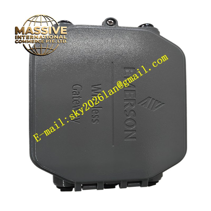
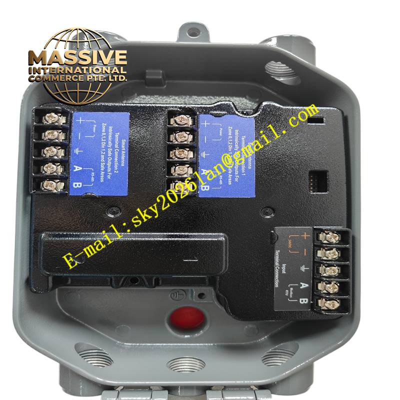
Emerson 1410S2AA32AD4N7RD
Technical Specifications HART protocol enabled; 4‑20mA DC analog output; stainless steel pressure sensing diaphragm; wide calibrated pressure span range; intrinsic safety and explosion proof certification options; ambient temperature compensation circuit; local digital display optional.
Functional Features Performs continuous high precision pressure measurement for process media. Supports remote configuration, range adjustment and diagnostic reading through HART handheld communicators. Temperature compensation circuitry eliminates measurement drift caused by ambient and process temperature changes. Built‑in self‑diagnosis identifies sensor faults, overrange conditions and electronics malfunctions.
Application Scenarios Oil and gas pipelines, chemical reaction vessels, boiler steam systems, water treatment pipelines and refinery process loops.
Performance Parameters High static pressure tolerance; low long term measurement drift; high resolution pressure conversion; stable signal output under industrial vibration conditions.
Material Composition Process wetted parts are stainless steel alloy; transmitter housing is cast aluminum with corrosion resistant coating; internal sensor chip is silicon piezoresistive element; electronic board substrate is FR‑4 flame retardant PCB; display window is scratch resistant polycarbonate.
Structural Characteristics Split style transmitter with separate sensing head and electronics housing; threaded process connection for pipeline mounting; rotatable electronics enclosure for convenient viewing orientation; external zero and span adjustment buttons; cable entry gland for field wiring.
Working Principle Process pressure acts on the metal isolation diaphragm and transfers pressure to the internal silicon piezoresistive sensor. The sensor generates a proportional millivolt signal. Onboard electronics amplify, temperature compensate and convert the signal to standard 4‑20mA current output superimposed with HART digital data.
Installation Requirements Mount the transmitter with proper orientation matching liquid or gas service requirements. Install isolation valves and drain manifolds for safe calibration and maintenance. Use shielded twisted pair signal cable with single point shield grounding. Complete zero calibration after installation and before commissioning.
Precautions for Use Do not apply pressure exceeding the maximum sensor overrange limit. Avoid exposing the transmitter to incompatible corrosive media not compatible with wetted material. Protect the housing from direct impact and prolonged chemical spray.