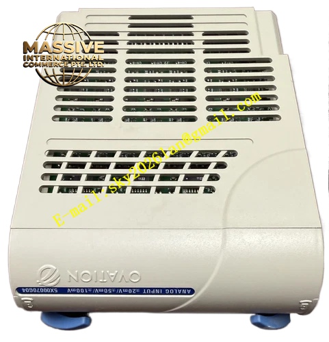
Description
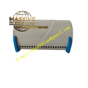
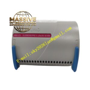
Emerson 1C31166G02
Technical Specifications
- Number of Input Channels: 8 analog input channels
- Input Signal: 4‑20mA analog current signal
- Isolation Type: Optical isolation between field side and DCS backplane
- Operating Ambient Temperature: 0℃ ~ 60℃
- Storage Temperature: -40℃ ~ 85℃
- Relative Humidity: 5% ~ 95%, non‑condensing
- Backplane Communication: Ovation proprietary DCS bus
- Enhanced channel‑level fault diagnosis and signal drift detection
Functional Features
High resolution analog‑to‑digital conversion circuit ensures accurate conversion of 4‑20mA field loop signals. Optical isolation isolates field instrument wiring and internal backplane circuit to restrain surge interference and common‑mode noise. Enhanced diagnostic circuit identifies wire break, short circuit and abnormal signal deviation of field loop. Front panel LED indicators display real‑time channel working status and module fault state. Rack plug‑in mechanical design supports hot swap under non‑critical process operating conditions.
Application Scenarios
Ovation DCS control cabinets in thermal power stations, chemical processing plants, pulp and paper mills. It receives analog measurement signals from pressure, flow, liquid level and temperature transmitters in process control loops.
Performance Parameters
Analog‑to‑digital conversion keeps stable high precision in full operating temperature range. Optical isolation bears high common‑mode voltage from long‑distance field instrument cables. Enhanced fault detection circuit captures subtle signal abnormality rapidly. Backplane bus communication realizes stable transmission of measurement data and diagnostic logs.
Material Composition
Flame‑retardant engineering plastic housing. Multi‑layer flame‑retardant glass fiber epoxy PCB. High‑precision analog‑to‑digital conversion chips, optical isolation chips, main processing microprocessor and LED status indicators. Gold plated copper alloy backplane connector. Supporting terminal base uses flame‑retardant PA plastic and nickel plated copper screw terminals.
Structural Features
Standard plug‑in card for Ovation DCS rack slots. Front panel fitted with module fault LED and separate LED indicators for each analog channel. Guide rails and mechanical latch lock module firmly inside equipment rack. Rear gold plated connector mates precisely with Ovation rack backplane bus. Matched front terminal base provides wiring interface for field transmitters.
Working Principle
Field transmitters output 4‑20mA analog current signals and transmit signals to module input channels through matched terminal base. Optical isolation chips separate field side circuit and DCS backplane circuit. High precision analog‑to‑digital converter converts analog current signal into digital measurement data. Digital data transmits to Ovation controller through backplane bus. Onboard sampling circuit continuously monitors signal value of each channel, triggers fault alarm and sends alarm message to DCS system when wire break, short circuit or signal drift is detected.
Installation Requirements
Insert module along rack guide rail into designated Ovation rack slot and lock mechanical latch. Adopt shielded twisted pair cables for field transmitter wiring. Cable shield applies single‑point grounding mode inside control cabinet. Keep analog signal cables separated from high‑voltage power cables. Reserve air circulation space for module heat dissipation.
Precautions for Use
Disconnect field transmitter power before wiring work. Calibrate channel measurement value after module replacement. Check signal cable insulation and terminal screw tightness regularly. Do not apply voltage exceeding rated range to input terminals. Do not disassemble module outer housing.