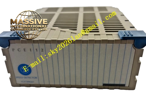
Description
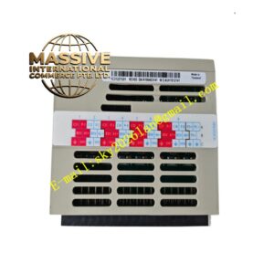
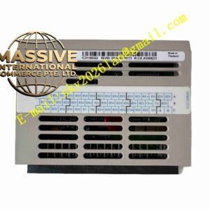
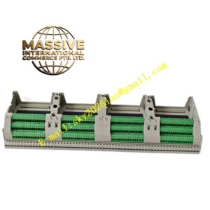
Emerson 1C31189G01
Technical Specifications
- Supported Signal: 4-20mA analog current signal
- Terminal Quantity: Matched with 8-channel analog input module
- Built-in surge suppression protection components
- Operating Ambient Temperature: 0℃ ~ 60℃
- Storage Temperature: -40℃ ~ 85℃
- Relative Humidity: 5% ~ 95%, non-condensing
- Mechanical Matching: Compatible with Ovation series analog input plug-in cards
- Screw type wiring terminals
Functional Features Screw terminals facilitate field instrument cable wiring and maintenance disassembly. Built-in surge suppression components absorb instantaneous surge voltage from long field cables. Internal signal traces transmit analog field signals to upper analog input module. Integrated short-circuit test terminals support on-site loop testing without removing wiring. Precise mechanical positioning ensures reliable electrical contact between terminal base and plug-in module.
Application Scenarios Ovation DCS control cabinets in thermal power plants, chemical factories and pulp and paper mills. It works with Ovation analog input modules to connect pressure, flow, liquid level and temperature transmitters.
Performance Parameters Signal traces keep low signal attenuation for 4-20mA analog transmission. Surge protection components absorb instantaneous high voltage pulse effectively. Screw terminals maintain stable electrical connection under cabinet long-term vibration. Mechanical contact part keeps consistent signal transmission after repeated module plugging.
Material Composition Main body uses flame-retardant PA engineering plastic. Nickel-plated copper alloy screw terminals. Multi-layer glass fiber epoxy PCB internal substrate. Solid-state surge suppression components. Metal positioning pins with anti-oxidation plating.
Structural Features Fixed installation base mounted on DIN rail inside control cabinet. Front side with multiple screw wiring terminals for field instrument cables. Top contact pins connect with analog input module bottom connector. Reserved test terminals for loop signal inspection. Positioning buckle ensures accurate alignment with plug-in module.
Working Principle Field analog signal cables connect to screw terminals of terminal base. Analog current signal passes through built-in surge protection circuit and internal PCB traces. Signal transmits upward through contact pins to analog input module plugged above. Surge suppression components absorb transient overvoltage from field cables to protect analog input module circuit. Test terminals lead out signal loop for on-site measurement and loop fault inspection.
Installation Requirements Mount terminal base on standard DIN rail inside control cabinet and lock fixed buckle. Route shielded twisted-pair field cables and fasten each terminal screw. Implement single-point grounding for cable shield wire inside cabinet. Confirm top contact pins fully contact with analog input module bottom connector after module insertion. Separate analog wiring from high voltage power wiring.
Precautions for Use Cut off field transmitter power before wiring modification. Check terminal screw tightness during regular cabinet inspection. Do not apply overvoltage to signal terminals. Keep contact pins clean without dust and metal debris. Do not modify internal circuit of terminal base.