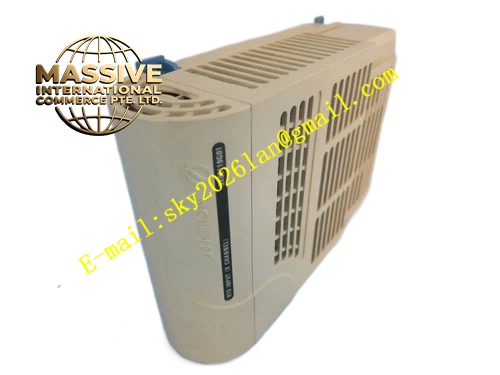
Description
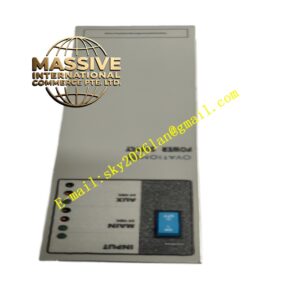
Emerson 1C31219G01
Technical Specifications
- Compatible hardware: Ovation analog output module
- Rated signal: 4-20mA analog current output
- Maximum working voltage: 30VDC
- Built-in transient overvoltage protection components
- Operating ambient temperature: 0℃ ~ 60℃
- Storage temperature: -40℃ ~ 85℃
- Relative humidity: 5% ~ 95%, non-condensing
- Wiring method: Screw clamping terminals
Functional Features Screw terminals provide stable clamping for field instrument wires. Built-in surge suppression components absorb transient voltage surges from long field cables. Reserved test jacks allow technicians to measure output current without disconnecting field wiring. Internal PCB traces realize one-to-one mapping between AO module channels and field terminals. Mechanical locking buckle achieves firm assembly between terminal base and analog output module.
Application Scenarios Ovation DCS control cabinets in thermal power plants, chemical plants and pulp factories. It provides wiring connection for control valve positioners, frequency converters and local analog indicators.
Performance Parameters Terminal clamping force maintains stable contact under cabinet vibration. Surge suppression circuit rapidly absorbs transient overvoltage pulses. Internal traces keep low signal attenuation for 4-20mA current signals. Terminals retain stable performance after repeated wiring operations.
Material Composition Housing uses flame-retardant PA engineering plastic. Internal circuit board adopts flame-retardant glass fiber epoxy PCB. Nickel-plated copper screw terminals. Integrated transient voltage suppression diodes and resistors. Contact pins use gold-plated copper alloy.
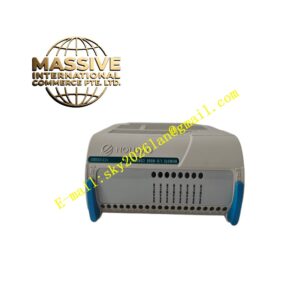
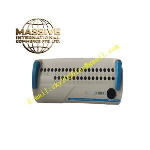
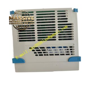
Structural Features Front assembly matched with Ovation analog output module. Multiple rows of screw wiring terminals arranged orderly. Independent test jack for each analog output channel. Mechanical locking buckle connects tightly with AO module. Rear contact pins mate with front connector of analog output card.
Working Principle 4-20mA analog current signals generated by AO module transmit to terminal base through contact pins. Signals pass through surge protection components and internal PCB traces, then reach field control devices connected to screw terminals. When surge overvoltage occurs on field cables, protection components divert surge energy to protective ground. Test jacks directly access output loop for on-site current measurement and loop debugging.
Installation Requirements Align terminal base connector with front connector of analog output module and fasten locking buckle. Strip wire insulation to specified length and tighten terminal screws with standard torque. Use shielded twisted pair cables for field control device wiring, implement single-point shield grounding inside cabinet. Avoid pulling stress on terminals during cable routing.
Precautions for Use Disconnect field instrument power before wiring. Do not over-tighten terminal screws. Inspect terminal tightness periodically. Prevent metal debris falling into terminal assembly. Do not apply voltage exceeding rated value to terminals.